www.scheppach.com service@scheppach.com +(49)-08223-4002-99 +(49)-08223-4002-58
26 І 56
Using the laser (Fig. 21)
To switch on: Move the ON/OFF switch (28) to the “I”
position to switch on the laser. Two laser lines are pro-
jected on the workpiece and intersect at the center of the
drill tip contact point.
To switch off: Move the ON/OFF switch (28) to the “0”
position.
Working light operation (Fig. 21/22)
Note: Always ensure good lighting at the work station
Switching on: Move the on/off switch (29) into the “I”
position to switch the working light (30) on.
Switching off: Move the on/off switch (29) into the “0”
position.
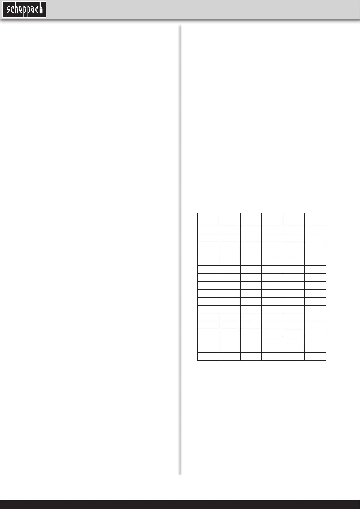
Working speeds
Ensure that you drill at the proper speed. Drill speed is
dependent on the diameter of the drill bit and the material
in question.
The table below acts as a guide for selecting the proper
speed for various materials.
Note: The drill speeds speci ed are merely sugges-
ted values.
Drill
bit Ø
Cast
iron
Steel Iron Alumi-
nium
Bronze
3 2550 1600 2230 9500 8000
4 1900 1200 1680 7200 6000
5 1530 955 1340 5700 4800
6 1270 800 1100 4800 4000
7 1090 680 960 4100 3400
8 960 600 840 3600 3000
9 850 530 740 3200 2650
10 765 480 670 2860 2400
11 700 435 610 2600 2170
12 640 400 560 2400 2000
13 590 370 515 2200 1840
14 545 340 480 2000 1700
16 480 300 420 1800 1500
18 425 265 370 1600 1300
20 380 240 335 1400 1200
22 350 220 305 1300 1100
25 305 190 270 1150 950
Countersinking and center-drilling
With this table drill, you can also countersink and center-
drill. Please observe that countersinking should be per-
formed at the lowest speed, while a high speed is requi-
red for center-drilling.
Drilling wood
Please note that sawdust must be properly evacuated
when working with wood, as it can pose a health hazard.
Ensure that you wear a suitable dust mask when perfor-
ming work that generates dust.
• Slowly and steadily move the speed control lever
(6) while the machine is in idle mode.
• Ensure that the machine can run without interrupti-
on (i.e. remove workpieces, drill bits, etc.).
Use the speed control lever (6) to in nitely adjust the
speed. The set speed is shown on the digital display (8)
in revolutions per minute.
Important! Never let the pillar drill run when the V-belt
cover is open. Always pull power plug before opening the
cover. Never touch the V-belt when it is rotating.
Drill depth stop (Fig. 16)
The drilling spindle has a swivelling scale ring (26) for
setting the drill depth. Only adjust the setting when the
equipment is at a standstill.
• Press the drilling spindle downwards until the tip of the
drill bit touches the workpiece.
• Slacken the clamping screw (25) and turn the scale
ring (26) forwards until it stops.
• Turn the scale ring (26) back to the desired drill depth,
then lock this setting into place using the clamping
screw (25).
Important! When setting the drill depth of a cylindrical
hole you must add the length of the drill tip.
Setting the angle of the drill table (Fig. 1/17)
• Slacken the carriage bolt (27) under the drill table (4).
• Set the drill table (4) to the desired angle..
• Tighten down the carriage bolt (27) in order to lock the
drill table (4) into this position.
Setting the height of the drill table (Fig. 18/19)
• Slacken the tightening screw (3).
• Set the drill table to the desired position with the help of
the hand crank (17).
• Screw the tightening screw (3) back down again.
Drill table and roll base (Fig. 20)
• Slacken the clamping screw (3) to turn the drill table
(4).
• Slacken the thumb screws (21) to extend the roll base
(13).
Clamping the workpiece
As a general rule, use a machine vice or another suitable
clamping device to secure a workpiece in position. Never
hold the workpiece in place with your hand! When drilling,
the workpiece should be able to travel on the drill table
(4) for selfcentering purposes. Ensure that the workpiece
cannot rotate. This is best achieved by placing the work-
piece /machine vice on a sturdy block.
Caution! Sheet metal parts must be clamped in to pre-
vent them from being torn up. Properly set the height and
angle of the drill table for each workpiece. There must be
enough distance between the upper edge of the workpie-
ce and the tip of the drill bit.
 Loading...