www.schischek.com
Schischek GmbH Germany, Muehlsteig 45, Gewerbegebiet Sued 5, 90579 Langenzenn, Tel. +49 9101 9081-0, Fax +49 9101 9081-77, E-Mail info-de@schischek.com
ExMax-S-Y_en
V01 – 16-Nov-2017
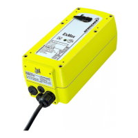
ExMax-...-Y ExMax-...-YF
Special options ... -CTS ... -VAS
Technical data ExMax- 5.10 -Y ExMax- 15.30 -Y ExMax- 5.10 -YF ExMax- 15 -YF
Approbations Special solutions and accessories
...-CTS Types in aluminium housing with seawater resistant coating,
parts nickel-plated
...-VAS Types in stainless steel housing, parts nickel-plated
ExBox-Y/S... Ex-e terminal boxes for zone 1, 2, 21, 22
MKK-S Mounting bracket for boxes type ...Box-... directly on actuator
ExSwitch 2 external aux. switches, adjustable for zone 1, 2, 21, 22
HV-S... Comfortable manual override for...Max actuators size S
KB-S Clamp for damper shafts Ø 10...20 mm and
□ 10...16 mm
AR-12-xx Reduction part for 12 mm square connection to 11, 10, 9 or 8 mm shafts
Kit-S8 Cable glands nickel-plated
Adaptions for dampers and valves on request
Torque motor (min.) 5 / 10 Nm selectable on site 15 / 30 Nm selectable on site 5 / 10 Nm selectable on site 15 Nm
Torque spring (F) – – min. 10 Nm min. 15 Nm
Torque blockade In blockade and end positions torques are higher than above specified torques for motor and spring.
Dimensioning of external load Upon spring return the external load should be max. 80 % of torque spring (F).
Supply voltage / frequency 24...240 V AC/DC, ± 10 %, self adaptable, frequency 50...60 Hz ± 20 %
Power consumption max. starting currents see
Extra information (in acc. with voltage, I
start
>> I
rated
), approx. 5 W holding power, approx. 16 W for heater
Protection class Class I (grounded)
Angle of rotation and indication 95° incl. ~ 5° pretension, mechanical value indication
Working direction Selectable by left/right mounting to the damper/valve shaft
Motor running times 7,5 / 15 / 30 / 60 / 120 s/90° selectable on site
Motor Brushless DC motor
Control mode Y 3-pos., 0…10 V DC, 4…20 mA in acc. with wiring, selectable on site. Galvanic separation between supply and Y-signal
Feedback signal U 0…10 V DC, 4…20 mA in acc. with wiring, selectable on site, both signals are available at the same time
Resistance of Y and U signals Input signal: Y
U
0...10 V DC at 10 kΩ, Y
I
4...20 mA at 100 Ω. Feedback signal: U
U
0...10 V DC at 2.000...∞ Ω, U
I
4...20 mA at 0...800 Ω
Reverse function Bridge between terminals 3–4 (signal line) effects a reverse function of input and output signals (Y and U)
Compulsion control In modulation mode an On-off compulsion control can be performed by external connection/wiring independently from the modulating signal
Adjustment of Y and U In case of external mechanical limitation of the angle of rotation, it is possible to perform an adjustment drive started by pushing the button (T)
Spring return (F) – – spring return upon voltage interruption
Spring return response time – – up to 1 sec. after voltage interruption
Spring return running time (F) – – ~ 3 or 10 s / 90° selectable on site
3 sec. mode – spring return – – ~ 3 to 4 s/90° angle of rotation acc. to external load
Safety operations at 10 sec. (F) – – min. 10,000 acc. to construction of damper and ambient
at 3 sec. (F) – – min. 1,000 acc. to construction of damper and ambient
Axle of the actuator Double square 12 × 12 mm, direct coupling, 100 % overload protected and self locking up to 15 Nm
Electrical connection 2 cable glands ~ 1 m each, wire cross section 0.5 mm², equipotential bonding 4 mm².
Connections in hazardous areas require an Ex-e terminal box!
Diameter of cable ~ Ø 7.1 + 7.4 mm ~ Ø 7.1 + 7.4 mm ~ Ø 7.4 mm each ~ Ø 7.4 mm each
Cable gland M16 × 1.5 mm
Manual override Use delivered socket wrench, max. 4 Nm
Heater Integrated, controlled heater for ambient temperature down to −40 °C
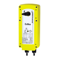
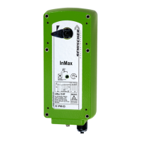
Housing material Aluminium die-cast housing, coated. Optional with seawater resistant coating (...-CTS) or stainless steel housing,
№ 1.4581 / UNS-J92900 / similar AISI 316Nb (...-VAS)
Dimensions (L × W × H) 210 × 95 × 80 mm, for diagrams see
Extra information
Weight ~ 3,5 kg aluminium housing, stainless steel ~ 7 kg
Ambients Storage temperature −40…+70 °C, working temperature −40…+40 °C at T6 and −40…+50 °C at T5
Humidity 0...90 % rH, non condensing
Operating 7,5 sec. motor run time at 24 V: S3 – 50 % ED intermittent mode (ED = duty cycle)
≥ 15 sec. motor run time at 15 / 30 / 60 / 120 s 100 % of ED is permitted
Accuracy electrically ~ 100 steps
Self adjustment Before initial operation you need to start the self adjustment mode for “gentle” blockade and adjustment of rotation angle
Wiring diagrams SB 5.0 / 5.1 / 5.2 / 5.3
Scope of delivery Actuator with 2 × 1 m cable, 4 screws M4 × 100 mm, 4 nuts M4, Allen key for simple manual override
Parameter at delivery 5 Nm, 30 s/90° 15 Nm, 30 s/90° 5 Nm, 30 s/90° 15 Nm, 30 s/90°
ATEX directive 2014/34/EU
EC type-approved PTB 04 ATEX 1028 X
IECEx certified IECEx PTB 07.0057X
Approval for gas II 2 (1) G Ex d [ia] IIC T6, T5
Types ...-CTS II 2 (1) G Ex d [ia] IIB T6, T5
Approval for dust II 2 (1) D Ex tD [iaD] A21 IP66 T80, T95°C
CE identification CE № 0158
EMC directive 2014/30/EU
Low voltage directive 2014 / 35 / EU
Enclosure protection IP66 in acc. with EN 60529
EAC № ТС RU С-DE.ГБ08.В.01510
2 / 4
 Loading...