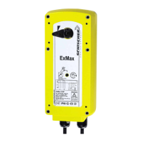
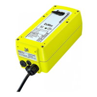
ExBox
Y: 0...10 V / 4...20 mA
U: 0...10 V / 4...20 mA
a
a
b
b
+
~
+
~
+
~
+
~
−
~
−
~
−
~
−
~
PE PE
PE PE
1 1
1 1
2 2
2 2
3 3
3 3
5 5
5 5
4 4
4 4
6 6
6 6
1 1
1 1
2 2
2 2
3 3
3 3
5 5
5 5
4 4
4 4
PA PA
PA PA
Y
mA
Y
mA
Y
mA
Y
V DC
Y
V DC
Y
V DC
T
V DC/mA
T
V DC/mA
T
V DC/mA
T
V DC/mA
U
mA
U
mA
U
mA
U
V DC
U
V DC
U
V DC
www.schischek.com
Schischek GmbH Germany, Muehlsteig 45, Gewerbegebiet Sued 5, 90579 Langenzenn, Tel. +49 9101 9081-0, Fax +49 9101 9081-77, E-Mail info-de@schischek.com
ExMax-S-Y_en
V01 – 16-Nov-2017
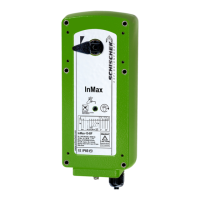
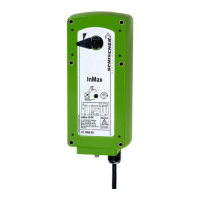
ExMax-...-Y ExMax-...-YF
Special options ... -CTS ... -VAS
Important information for installation and operation
Electrical connection
All actuators are equipped with a universal supply unit working at a voltage range from
24...240 V AC/DC. The supply unit is self adjusting to the connected voltage!
The safety operation of the spring return function works if the supply voltage is cut.
For electrical connection inside hazardous areas an Ex-e terminal box, certificated in acc.
Installation
Ex area –
zone 1, 2, 21, 22
Safe area
Supply *
24...240 V AC/DC ± 10 %
* electrical wiring see diagrams
with ATEX is required (e.g. ExBox).
An over-current protection fuse < 10 A has to be provided by installer.
Note: the initial current is appr. 2 A for 1 second.
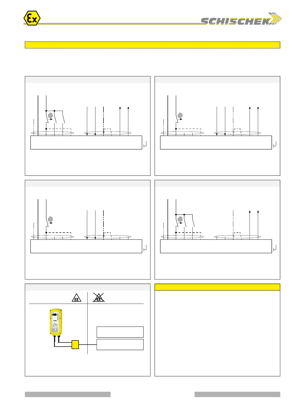
Modulating – with / without spring return (no feedback) SB 5.2 3-pos. – with / without spring return + feedback SB 5.3
Modulating / 3-pos. – with / without spring return SB 5.0 Modulating – with / without spring return (no enforcement) SB 5.1
Selection of running time for spring return:
Spring return in ~ 10 s = Standard wiring
Spring return in ~ 3 s = Additional wiring on terminal 5
Selection of running time for spring return:
Spring return in ~ 10 s = Standard wiring
Spring return in ~ 3 s = Additional wiring on terminal 5
Selection of running time for spring return:
Spring return in ~ 10 s = Standard wiring
Spring return in ~ 3 s = Additional wiring on terminal 5
Selection of running time for spring return:
Spring return in ~ 10 s = Standard wiring
Spring return in ~ 3 s = Additional wiring on terminal 5
3-pos. control mode:
▪ a closed, b open – ON (OFF) in acc. to left/ right mounting of actuator
▪ b closed, a open – OFF (ON) in acc. to left/ right mounting of actuator
Function and enforcement control of switch a and b in modulating mode:
▪ a closed – Forced-ON (OFF) in acc. to left/ right mounting of actuator
▪ b closed – Forced-OFF (ON) in acc. to left/ right mounting of actuator
Reverse function:
Bridge 3– 4 reverses
the input signals
Reverse function:
Bridge 3– 4 reverses
the output signals
Reverse function:
Bridge 3– 4 reverses the
input and output signals
Reverse function:
Bridge 3– 4 reverses the
input and output signals
Self adjustment:
To adjust the signal input /output to the angle of
rotation of the damper/ valve the button (T) must
be pushed for a minimum of 3 sec.
Self adjustment:
To adjust the signal input /output to the angle of
rotation of the damper/ valve the button (T) must
be pushed for a minimum of 3 sec.
Self adjustment:
To adjust the signal input /output to the angle of
rotation of the damper/ valve the button (T) must
be pushed for a minimum of 3 sec.
Self adjustment:
To adjust the signal input /output to the angle of
rotation of the damper/ valve the button (T) must
be pushed for a minimum of 3 sec.
Attention!
When changing 3-position
mode into modulating
regard function, see
page 4 – Parametrisation D)
24...240 V AC/DC 24...240 V AC/DC
24...240 V AC/DC 24...240 V AC/DC
A. Installation, commissioning, maintenance
All national and international standards, rules and regulations for hazardous Ex-areas
must be complied. Certified apparatus must be installed in accordance with manufacturer
instructions. If the equipment is used in a manner not specified by the manufacturer,
the safety protection provided by the equipment may be impaired. For electrical
installations design, selection and erection, EN/IEC 60079-14 can be used.
For electrical connection an Ex-e terminal box is required (e.g. ExBox-...).
Attention: If the actuator is put out of operation all Ex rules and regulations must be
applied. You have to cut the supply voltage before opening the terminal box!
The cables of the actuator must be installed in a fixed position and protected against
mechanical and thermical damage. Connect potential earth. Avoid temperature transfer
from armature to actuator! Close all openings with min. IP66.
For outdoor installation a protective weather shield against sun, rain and snow should
be applied to the actuator as well as a constant supply at terminal 1 and 2 for the
integrated heater. During commissioning apply a self adjustment drive.
Actuators are maintenance free. An annual inspection is recommended. For electrical
installations inspection and maintenance, EN/IEC 60079-17 can be used. Ex-actua-
tors must not be opened by the customer.
B. Manual override
Manual override only if supply voltage is cut. Use delivered socket wrench with slow
motions, usage can be tight. Attention: Releasing or letting go the Allen key too fast
at manual operating actuators with spring return causes risk of injury!
C. Shaft connection, selection of running time
Actuators are equipped with a direct coupling double square shaft connection of
12 × 12 mm. For round shafts adaptors/clamping connection (accessories, e.g. KB-S)
are available. The housing of the actuator is axially symmetrically built to select Open-close
direction of the spring return function by left-right mounting. Using the 10-position switch
different motor running times and spring return running times can be selected on site
in acc. to the actuator type.
D. 3-position control mode
...Max actuators are in the best way suitable for the 3-pos. operation. To protect such
elements as gears and mounting elements against harmful influences like minimum
pulse time, ...Max actuators are protected via internal electronics. It ignores impulses
< 0.5 s, the cyclic duration must be min. 0.5 s. At changing direction the pause is 1 s.
E. Spring return
Spring return function works only if the supply voltage for terminal 1 or 2 is cut. In the
event of an electrical interruption, the spring returns to its end position even if supply
voltage is available again during return function. Thereafter operation will continue.
F. Operation at ambient temperatures below −20 °C
All actuators are equipped with a regulated integrated heating device designed for
employments down to −40 °C ambient temperature. The heater will be supplied
automatically by connecting the constant voltage supply on the clamps 1 and 2.
1. After mounting the actuator must bei immediately electrically connected.
2. The heater switches on automatically when actuator reaches internally −20 °C. It
heats up the actuator to a proper working temperature, then heater switches off auto-
matically. Actuator will not run during heating process.
3. The adjustment options are only ensured after this heating up period.
G. Excess temperatures
In acc. to the ATEX rules and regulations Ex actuators must be protected against excess
temperature. The internal thermostat works as a maximum limiter and, in the event of
failure at incorrect temperatures, shuts off the actuator irreversible. An upstream
connected temperature sensor stops the actuator before reaching its max. temperature.
This safety feature is reversible, after cooling down the actuator is completely functional
again. In this case the failure must be eliminated immediately on site!
H. Synchron mode
Do not connect several actuators to one shaft or link mechanically together.
I. Mechanical protection
Actuators must be operated with a minimum external load.
After installing the actuator to the damper/armature a self adjustment drive has to be
performed in order to protect the damper/armature against mechanical overload.
During operation the actuator reduces briefly its speed (motor power) before reaching
the end position for a “gentle” blockade/stop.
J. Intrinsically safe circuits
The actuator has a flameproof enclosure acc. to EN 60079. The supply of the push
button (adjustment drive), the 10-position switch (adjustment of torque and running
time) and the LED indicator is performed intrinsically safe!
continue next page
3 / 4
 Loading...