Do you have a question about the Schleuniger CrimpCenter 64 SP and is the answer not in the manual?
Provides manufacturer contact details and website.
Specifies the machine models this manual applies to.
Directs users to the rating plate for product identification.
Explains the manual's purpose, scope, and intended use.
Details the manual's structure, including operating, software, and parts catalog sections.
Instructions on keeping operating instructions protected and accessible.
Defines responsibilities for keeping the handbook near the product and following instructions.
Explains the meaning of symbols, mark-ups, and abbreviations used throughout the manual.
Defines pictograms used for information, overview, recycle, and disposal.
Explains text formatting for commands, screen titles, and cross-references.
Notes that illustrations may differ from the actual product due to ongoing improvements.
Refers to separate documents for conformity and incorporation declarations.
States the manufacturer's disclaimer for damages resulting from improper use or disregard of instructions.
Directs users to the "General Conditions of Sale and Delivery" document.
Outlines confidentiality requirements and copyright protection of the manual's content.
Lists registered trademarks like Windows® and other product names.
Advises obtaining original spare parts and warns about risks of unverified parts.
Prohibits modifications and misuse, warning of guarantee loss.
Emphasizes proper handling and disposal of substances like lubricants and solvents.
Details Schleuniger's personal data processing and provides links to privacy statements.
Provides contact information for technical problems, service, and training inquiries.
Advises contacting local service partners for safety and security updates.
Specifies required qualifications for personnel operating the machine.
Classifies personnel roles such as Operating Company, Schleuniger GmbH Specialist, and Third Person.
Assigns specific tasks and authorities to different personnel groups.
Defines responsibilities of the legal entity and employees for safe operation and training.
Explains the meaning and significance of DANGER, WARNING, CAUTION, and NOTICE symbols.
Defines the product's intended applications and prohibits unauthorized modifications.
Lists potential misuses and materials that should not be processed.
Emphasizes the importance of observing and maintaining safety markings on the product.
Explains safety symbols used in the manual to alert users to potential hazards.
Specifies required personal protective equipment (PPE) for hazard mitigation.
Details the necessity of eye protection against particles during stripping and cutting.
Advises on wearing tight-fitting clothes to prevent entanglement with moving parts.
Recommends wearing safety shoes to protect against falling objects.
Advises wearing cut-resistant and heat-resistant gloves for hand protection.
Recommends wearing snood-type caps to prevent hair from getting caught.
Lists essential safety regulations, including age limits and operational guidelines.
Identifies potential dangers such as entanglement, tripping, and noise hazards.
Stresses the importance of not tampering with or bypassing built-in safety devices.
Prohibits unauthorized modifications to the product and software without manufacturer permission.
Provides critical safety instructions for transporting the product.
Warns against unauthorized transport and emphasizes qualified personnel involvement.
Advises careful handling and adherence to packaging symbols during transport.
Explains the meaning of various packaging symbols for proper handling.
Outlines the procedure for inspecting the delivery for damages and completeness.
Provides instructions for safely unpacking the machine and removing transport fixations.
Identifies the correct positions for lifting the machine using handling devices.
Instructions for storing and disposing of packaging materials properly.
Guidance on storing packaging materials in a weatherproof location.
Information on recycling packaging materials according to environmental standards.
Advises transporting the machine in its original packaging when applicable.
Specifies conditions for product storage to prevent damage and ensure longevity.
Presents a table detailing the machine's physical dimensions and weight.
Lists key technical specifications including processing stations, wire range, and power requirements.
Provides essential data for planning the machine's installation site and connections.
Details requirements for the installation site, including temperature and humidity.
Specifies the required electrical voltage, frequency, and air pressure.
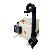
Illustrates the location of power supply and pneumatic units on the machine.
Identifies different operational zones within the machine.
Explains the information presented on the machine's rating plate.
Gives a general introduction to the CrimpCenter 64 SP and its capabilities.
Describes the essential components and functions included in the standard machine configuration.
Details the basic processing capabilities like measuring, cutting, stripping, and sealing.
Explains quality assurance features such as length measuring wheels and good/bad part sorting.
Lists various optional stations and accessories that enhance machine functionality.
Describes specific optional processes like crimping, sealing, and coaxial processing.
Provides comprehensive details on available stations, options, and software.
Lists and describes stations like UniCrimp, SealLoad, and twisting/tinning stations.
Details optional features such as fingerprint readers and barcode scanners.
Describes software enhancements like EASY ProductionServer and NetConverter.
Mentions the depositing table for additional devices like PullTesters.
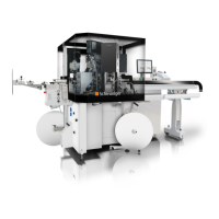
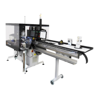
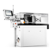
Presents examples of machine configurations with labeled components.
Illustrates a configuration including sealing, crimping, and quality assurance modules.
Shows a configuration with sealing and crimping stations.
Displays a configuration focused on crimping stations.
Lists the components included in the product delivery and required basic equipment.
Itemizes the components part of the product scope of delivery.
Lists essential equipment not included with the product but necessary for operation.
Explains the operation of the main switch for turning the machine on and off.
Details the function and locations of the emergency stop buttons on the machine.
Describes the safety cover's protective function and operation.
Explains the safety switch mechanism and its role in machine operation.
Provides instructions on operating the safety cover pushbuttons.
Explains the function and locations of confirm buttons used for setup and rigging operations.
Identifies hazardous zones on the machine and emphasizes the need for PPE.
Details specific hazards present in areas like the wire feed and control cabinet when the cover is closed.
Identifies hazards when the safety cover is opened.
General safety guidelines to be followed during installation and commissioning.
Procedures for positioning and removing/installing machine components and accessories.
Instructions for removing and reinstalling the upper bracket transport aid.
Steps for dismantling and mounting transport aids for the Dual ToolingShuttle.
Guidance on installing and removing the wire straightener unit.
Safety procedures for disconnecting and removing the conveyor belt module.
Instructions for mounting and dismantling the optional Dual ToolingShuttle.
Safety precautions and requirements for electrical connections.
Diagrams illustrating control cabinet connections and interface assignments.
Instructions for accessing and working within the control cabinet.
Safety considerations and procedures for installing and managing processing stations.
Detailed steps for opening and closing the safety cover using the machine interface or CommandPod.
Explains the locations and functionality of the confirm buttons used during setup.
Describes the functions and controls of the CommandPod for machine setup.
Explains the function of the Towerlight for indicating machine status.
Details the meaning of each LED element (siren, red, yellow, green, blue) on the Towerlight.
Describes the function of the service switch and its effect on the blue LED.
Explains the standard and custom configurations for Towerlight signals in the EASY software.
Guides users on configuring Towerlight signals and states within the EASY software.
Provides recommended settings for pneumatic and gripper pressure.
Discusses factors influencing optimal pneumatic pressure and gripper settings.
Lists all prerequisite conditions that must be met before starting the CrimpCenter.
A comprehensive guide to commissioning the machine and its stations.
Introduces the commissioning process and its affected areas.
Highlights specific safety instructions and potential dangers related to commissioning stations.
Lists necessary preparations and checks before starting the step-by-step commissioning.
Detailed instructions for aligning the machine using spirit levels and measuring tapes.
Procedures for setting up, inserting, and aligning conveyor belt modules.
Explains the function and safe usage of the ToolingShuttle for quick applicator changes.
Describes the process of switching between material feeders using the Dual ToolingShuttle.
Instructions for adjusting the working height of UniCrimp stations for operation.
Step-by-step guide to powering on and starting the CrimpCenter and EASY software.
Guidance on selecting and installing the correct wire guide tubes for production.
Instructions for passing the wire through the straightener and detecting knots.
Details how to set the wire feed contact pressure using the EASY software.
Instructions for adjusting the gripper clamping force via the EASY software.
Explains conveyor belt functions, potential risks, and operational controls.
Describes the process of referencing machine components for accurate positioning and calculation.
Introduces the servicing and maintenance section, outlining its contents.
General safety advice applicable to all maintenance and repair activities.
Crucial safety steps to follow before, during, and after maintenance work.
States that only qualified technical specialists are permitted for maintenance.
Emphasizes the mandatory use of PPE during maintenance tasks.
Provides contact information and procedures for customer support.
Advises contacting local representatives for technical assistance.
Lists essential information required for effective troubleshooting support.
Provides a comprehensive table of maintenance tasks, intervals, and durations.
Details the maintenance procedures for checking various safety devices.
Outlines the annual task of checking and logging all security elements.
Procedure for checking the main switch for damage, secure fit, and proper function.
Instructions for verifying the condition and function of emergency stop switches.
Procedure for checking confirm buttons for damage, secure fit, and functionality.
Steps for checking the safety cover open/close button's condition.
Procedure for verifying the safety switch's operation when the cover is opened or closed.
Details how to check the safety cover's closing force using a spring balance.
Instructions to verify the safety mechanism that reopens the cover when lowered.
Procedure for checking the standstill monitoring of the machine's motors.
Steps to test if servo motors switch off powerlessly when an axis deviates from its position.
Maintenance procedure for the pneumatic main shut-off valve.
Instructions for checking the main shut-off valve of the pneumatic system.
Procedure for checking the conveyor belt for damages and wear.
Steps to inspect the conveyor belt for functioning and wear at its end.
Instructions for checking power sockets for damage, secure fit, and function.
Procedure for checking all existing power sockets against DGUV-V3 standards.
General machine check for technical intactness and completeness.
Outlines the task of checking and logging the entire machine's technical condition.
Instructions for cleaning and maintaining various machine surfaces.
Details the process for cleaning and caring for different surface types on the machine.
Instructions for lubricating the cutting unit's guide rails and ballscrews.
Procedure for lubricating the cutting unit's moving parts.
Instructions for cleaning cutter blocks and removing residues.
Steps for checking and cleaning cutter blocks for contamination.
Procedure for removing cutter blocks and replacing blades.
Detailed steps for safely changing the cutting and stripping blades.
Instructions for removing and installing new feeding belts on the wire feed unit.
Procedure for replacing the feeding belts on the wire feed unit.
Instructions for checking and draining condensate from the pneumatic unit.
Steps for checking and draining accumulated condensate from the water separator.
Instructions for cleaning or replacing pneumatic filters.
Procedure for removing, cleaning, or replacing pneumatic unit filters.
Instructions for checking, cleaning, or replacing control cabinet fan filters.
Steps for checking and maintaining filter mats on control cabinet fans.
Procedure for checking the conveyor belt for damages and wear.
Instructions to inspect the conveyor belt for any signs of damage or wear.
Provides step-by-step instructions for safely decommissioning the machine.
Guidelines for disassembling and disposing of machine parts according to legal regulations.
| Type | Automatic Crimping Machine |
|---|---|
| Connectivity | Ethernet, USB |
| Number of Processing Stations | Up to 6 |
| Crimp Force Monitoring | Yes |
| Power Supply | 3 x 400 VAC, 50/60 Hz |
| Air Pressure | 6 bar |
| Control System | Touchscreen with intuitive interface |
| Programs Storage | Unlimited |