Montageanleitung / Betätiger
Mounting instructions / Actuators
Instructions de montage / Actionneurs
AZM 161
Hinweis
Verwenden Sie als Sicherung gegen unbefugtes Lösen Sicherheits-
schrauben mit Einwegschlitz (als Zubehör erhältlich). Bei Befesti-
gung, z.B. durch Nieten oder Schweißen, ist darauf zu achten,
dass sich die Eintauchtiefe des Betätigers nicht ändert.
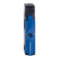
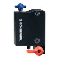
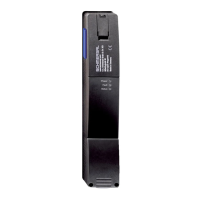
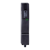
Es stehen verschiedene Betätigerformen zur Verfügung: Vorzugsweise
für verschieb- und abnehmbare Schutzeinrichtungen der Betätiger
AZM 161-B1 und AZM 161-B1E. Für drehbare Schutzeinrichtungen
der Betätiger AZM 161-B6.
Montage
Bei der Montage an drehbaren Schutzeinrichtungen ist darauf
zu achten, dass der Drehpunkt in der Ebene der Oberfläche des
Sicherheitsschalters liegt, in die der Betätigungsbügel eintaucht
(s. Tabelle).
Einstellschraube
Werkseitig ist der Betätiger AZM 161-B6 auf den kleinsten Radius
eingestellt. Bei größeren Radien erfolgt die Einstellung durch Drehen
der Einstellschrauben a + b mit einem Innensechskant-Schlüssel
SW 2,5 mm.
Notice
Please ensure this is fitted the correct way round, and tighten the
actuator with one-way screws (available as accessory), to prevent
deliberate removal. Please ensure with welding or riveting of the
actuator, that the insertion depth of the actuator is not altered.
There are different actuator types available, depending on the appli-
cation. The actuator AZM 161-B1 and AZM 161-B1E are designed
for sliding and removable safety guards, while AZM 161-B6 is
recommended for hinged safety guards.
Mounting
Please note, that the centre of rotation must be in the same plane
as the upper edge of the safety switch (see table).
Set screw
The basis setting of actuator AZM 161-B6 provides a minimum
radius. For larger radii, the angle has to be adjusted correspondingly
by turning the set screws a + b, using an hexagonal key wrench
2.5 mm A/F.
Remarque
Pour éviter tout démontage intempestif, utiliser les vis à tête fraisée
avec vissage unidirectionnelle (peut être fourni comme accessoire).
En cas de fixation selon un mode différent, par exemple par rivetage
ou soudage, veiller à ce que la profondeur de plongée de l'acionneur
ne varie. Different formes d’actionneurs sont disponibles. Les
actionneurs AZM 161-B1 et AZM 161-B1E sont recommandés pour
les protecteurs coulissants et amovibles. Dans le cas de protecteurs
pivotants, nous vous conseillons l’actionneur AZM 161-B6.
Montage
Lors du montage sur des protecteurs pivotants, veiller à ce que
l'axe de rotation se trouve dans le plan de la surface de l'inter-
rupteur de sécurité dans laquelle l'actionneur plonge (voir table).
Vis de réglage
Le réglage de base AZM 161-B6 est établi en fonction du plus petit
rayon. Dans le cas de rayons plus grands, modifier le réglage en
tournant la vis de réglage a + b à l'aide d'une clé 6 pans de
2,5 mm sur plats.
deutsch
english
français
Der Drehpunkt des Scharniers und Oberkante des Sicherheits-
schalters müssen zuzüglich x mm eine Ebene bilden. Die Grund-
einstellung ist auf den kleinsten Radius R
min
eingestellt.
The axis of the hinge must be x mm above and in a parallel plane
to the top surface of the safety switch. The basis setting provides
a minimum radius of R
min
.
L'axe de rotation de l'articulation et la face supérieure de l’inter-
rupteur de sécurité doivent se situer dans deux plans parallèles
distants de x mm. Le réglage de base est établi en fonction du
plus petit rayon, R
min
.