Schücode Commissioning instructions – Schüco DCS Touch Display
18
Dok-Nr.10000432116_01
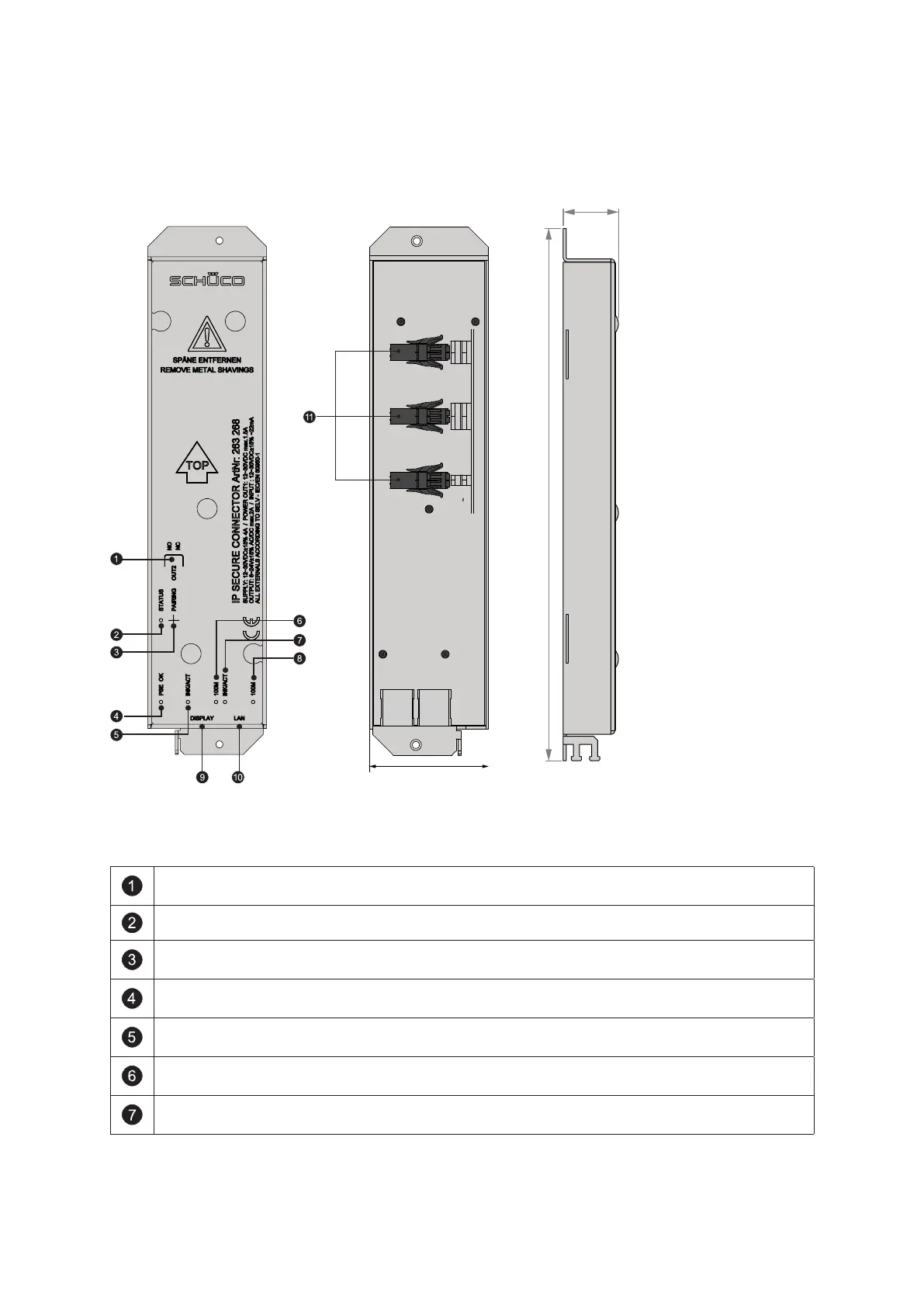
6.1. Overview of IP secure connector
SUPPLY
DC-OUT1
DC+
+
-
DC-
OUT1
OUT2
NO/NC
NO
COM
COM
IN1
IN2
+
+ -
-
12-30VDC
22mA
6-24V
AC/DC
max. 2A
12-30VDC
max. 1,5A
12-30VDC
max. 4A
FRONT VIEW
Front view Rear view
Side view
alle Maße in mm
Using the „OUT2“ switch, you can select whether the „OUT2“ relay is to function as a closer
(NO/Normally Open) or as an opener (NC/Normally Closed).
The „STATUS“ LED indicates the status of the IP secure connector (see the following table).
By pressing the „PAIRING“ button, the IP secure connector can be paired with a
DCS Touch Display.
The „PSE OK“ LED indicates the PoE status. If it is permanently lit, then there is a PoE+
power supply at the „DISPLAY“ RJ45 socket.
The „INK/ACT“ LED indicates whether data is being transmitted between the „DISPLAY“ RJ45
socket and the building’s internal switch.
The „100M“ LED indicates whether a transmission speed of 100 Mbps has been achieved
between the IP secure connector and the DCS Touch Display at the „DISPLAY“ RJ45 socket.
The „INK/ACT“ LED indicates whether data is being transmitted between the „LAN“ RJ45
socket and the building’s internal switch.
 Loading...