Schücode Commissioning instructions – Schüco DCS Touch Display
20
Dok-Nr.10000432116_01
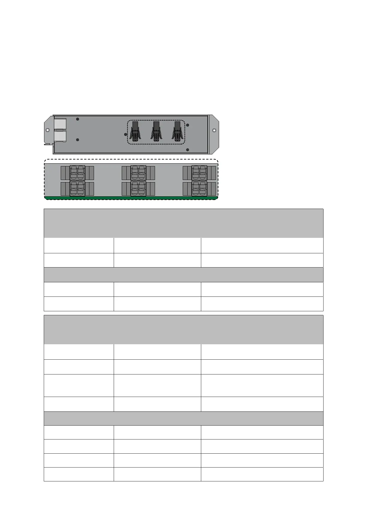
6.2. Connections for Schüco IP secure connector
The connections are located on the rear of the IP secure connector. The corresponding connectors
are supplied with the product or are included in the cable kits.
The inputs and outputs on the rear of the IP secure connector are assigned as follows:
IN2
+
–
+
–
+
–
+
–
NO COM
NO/
NC
COM
IN1
OUT2
OUT1
DC-OUT3
SUPPLY
Voltage range Notes
Power supply
SUPPLY+ 12–30 VDC (max. 4 A)
Max. 30 V DC Recommended power pack
Art. No. 263 099 24 V 2 A
SUPPLY– GND
Output
DC-OUT3+ 12–30 VDC (max. 1,5 A) Contact with potential
DC-OUT3– GND
Voltage range Notes
Relay
OUT1 NO 6–24 VAC/VDC (max. 2 A)
Potential-free contact Normally open
(closer) max. 60 V DC
OUT1 COM
OUT2 NO/NC 6–24 VAC/VDC (max. 2 A)
Potential-free contact Normally Open
(closer) or Normally Closed (opener) can
be set via the „OUT2“ switch
OUT2 COM
Inputs
IN1+ 12–30 VDC (~ 22 mA) Galvanically isolated
IN1– GND
IN2+ 12–30 VDC (~ 22 mA) Galvanically isolated
IN2– GND
 Loading...