schunk.com/downloads
MMS 22-PI1-EX
Magnetic switch
Commissioning instructions
SCHUNK SE & Co. KG
Toolholding and Workholding | Gripping Technology |
Automation Technology
D-74348 Lauffen/Neckar | Bahnhofstr. 106 - 134
Tel. +49-7133-103-0 | info@de.schunk.com | schunk.com
The sensor MEK-E22 is distributed exclusively by SCHUNK under the type
designation MMS 22...-EX/MMSK 22...-EX.
Manufacturer:
Bernstein AG
Hans-Bernstein-Str. 1
32457 Porta Westfalica, Germany
Copyright:
This document is protected by copyright.
The author is SCHUNKSE&Co.KG. All rights reserved.
Technical changes:
We reserve the right to make alterations for the purpose of technical
improvements.
Document number: 1564873
Version: 02.00|18/09/2023|en
1 About this manual
This short manual contains information regarding the assembly and initial operation.
Before starting work, the personnel must have read and understood this
operating manual. Prerequisite for safe working is the observance of all safety
instructions in this manual.
Further information can be found in the assembly and operating manual, which
can be downloaded from schunk.com/downloads.
2 Assembly and settings
2.1 Special conditions for ATEX applications
The sensor should be installed so that it is protected from UV light, mechanical
hazards, condensation and ingress of moisture.
The sensor must be provided with a fuse that corresponds to the rated current.
The breaking capacity of the fuse must correspond to the possible short circuit
current of the supply source.
For MMS(K) 22-PI1...EX, the fixed connection cable should be connected in non-
explosive areas or in a certified housing in compliance with an ignition
protection type according to EN 60079-0 or in a certified housing according to EN
60079-31.
2.2 Mechanical connection
CAUTION
Property damage due to incorrect bending radius!
The product may get damaged if the cable's bending radius is less than the
minimum.
l
Static: 10 times the cable diameter.
l
Dynamic: 15 times the cable diameter.
CAUTION
Risk of damage to the sensor during assembly!
l
Observe the maximal tightening torque.
Ferromagnetic components change the sensor's switching positions, e.g.
adapter plate made of construction steel. For ferromagnetic adapter plates:
– First, install the module on the adapter plate.
– Then adjust the switching position of the sensor.
NOTE
l
Do not use the sensor as a safety component.
l
Do not pull on the cable of the sensor.
l
Secure the cable and connection plug so that they are not taught and cannot
move during operation.
l
Do not exceed the permitted bending radius of the cable.
l
Do not allow the sensor to come into contact with hard objects and chemicals
(e.g., nitric acid, chromic acid and sulfuric acid).
The sensor is an electronic component that can be sensitive to high-frequency
interference or electromagnetic fields.
– Check whether there is sufficient distance between the sensor and sources of
interference and their supply cables.
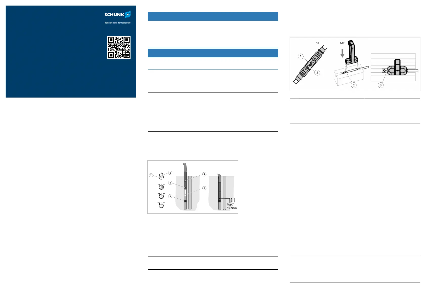
2.3 Installing and connecting the sensor
Mechanical connection
1. Turn the sensor (1) into the groove (2)
Or: Push the sensor (1) into the groove (2) until it reaches the clamping stop.
2. Secure the sensor (1) using the set-screw.
ð Observe the maximum tightening torque of 10Ncm.
3. Connect the sensor (1) and fasten the cable.
2.4 Adjusting the sensor
Adjusting switching points in teach mode
NOTE
The difference between the teach and operating temperatures must not exceed 30 K.
1. Place the module in switching position.
2. Place the magnet teach tool (MT) on the sensor (3) for at least 2s.
Or: Press the button (1) on the connector teach tool (ST) for at least 2s.
ð The LED (2) flashes after 2s.
3. Remove the MT.
Or: Release the button (1) on the ST.
4. Place the MT back on the sensor (3) for at least 0.3s, then remove it.
Or: Press the button (1) on the ST for at least 0.3s and then release it.
5. Wait 2s.
ð The LED (2) lights up continuously.
ST Plug teaching tool MT Magnet teaching tool
NOTE
The setting procedure is canceled after 30s if the MT is not placed on the sensor
again or the button (1) on the ST is not pressed. The LED (2) flashes quickly for 2s if
the magnetic field is too large or too small. If there is a duplicate or unsuitable
switching point, the sensor (3) should be moved by 2mm and taught again.
Displaying the optimal position
1. Place the module in switching position.
2. Insert the sensor (3) into the groove in teach mode until the LED (2) flashes
quickly.
Setting the hysteresis
The switch-off point of the end position can be manually adjusted by adjusting
the hysteresis.
A minimum and maximum hysteresis is defined based on the magnetic field.
This defines the distance between the switch-on and switch-off point. The
sensor prevents a hysteresis that is too low when the hysteresis is adjusted. If the
switch-off point is taught too far away from the switch-on point, the switch-off
position close to the switch-on point is automatically used. The switch-off point
must then be taught closer to the switch-on point.
1. Place the module in Switch-off point position.
2. Place the MT on the sensor (3) for at least 5s.
Or: Press the button (1) on the ST for at least 5s.
ð The LED (2) flashes after 2 to 5s and goes out.
3. Remove the MT quickly.
Or: Release the button (1) on the ST.
ð The LED (2) lights up to show the current switching point, otherwise the LED
(2) flashes.
4. Place the MT back on the sensor (3) for at least 0.3s, then remove it quickly.
Or: Press the button (1) on the ST for at least 0.3s.
5. Wait 2s.
ð After approximately 2s, the LED (2) flashes twice if the magnetic field is not
too large, otherwise it flashes quickly for 2s.
NOTE
A minimum and maximum hysteresis is defined based on the magnetic field. This
defines the distance between the switch-on and switch-off point. If the switch-
off point is taught too far away from the switch-on point, the switch-off position
close to the switch-on point is automatically used. In this case, the switch-off
point closer to the switch-on point must be taught.
 Loading...