Home
Schweitzer Engineering Laboratories
Relays
SEL-351S
Page 74
Schweitzer Engineering Laboratories SEL-351S - Page 74
636 pages
Manual
Save Page as PDF
To Next Page
To Next Page
To Previous Page
To Previous Page
Loading...
3-4
Overcur
rent, Volt
age, Sync
hronis
m Check,
Frequenc
y, a
nd
Power Elem
ents
Date Code 2
0010112
SEL-351S I
nstruc
tion Manual
)LJXUH/
HYHOV
WKURXJK
3KDVH,QV
WDQWDQHRX
V'HILQ
LWH7L
PH2YH
UFXUU
HQW(OHP
HQWV
:LWK'LUHF
WLRQDO&RQ
WURO
2SWLRQ
73
75
Table of Contents
Main Page
Cover Page
1
Manual Change Information
3
Table of Contents
9
Section 1: Introduction and Specifications
11
INTRODUCTION AND SPECIFICATIONS
13
SEL˚351S Relay Models
13
Instruction Manual Sections Overview
14
Applications
18
Hardware Connection Features
19
Communications Connections
22
General Specifications
23
Processing Specifications
27
Relay Element Pickup Ranges and Accuracies
28
Instantaneous/Definite-Time Overcurrent Elements
28
Time-Overcurrent Elements
28
Under- and Overvoltage Elements
29
Synchronism-Check Elements
29
Under- and Overfrequency Elements
29
Timers
29
Substation Battery Voltage Monitor
29
Metering Accuracy
30
Power Element Accuracy
31
Section 2: Installation
33
INSTALLATION
35
Relay Mounting
35
Rear-Panel Connection Diagrams
36
Making Rear-Panel Connections
42
Required Equipment and General Connection Information
42
Models 0351SxY (Plug-In Connectors)
42
Wiring Harness
42
Model 0351Sx1 (Screw-Terminal Blocks)
43
Chassis Ground
43
Model 0351SxY
43
Model 0351Sx1
43
Power Supply
43
Model 0351SxY
43
Model 0351Sx1
44
Output Contacts
44
Extra I/O
44
44
Standard Output Contacts
44
High-Current Interrupting Output Contacts
44
Optoisolated Inputs
45
SEL-351S Model 0351Sxxx5 Auxiliary Trip/Close Pushbuttons and Open/Closed LEDs
45
Current Transformer Inputs
45
Model 0351SxY
45
Models 0351Sx1
46
Potential Transformer Inputs
46
Model 0351SxY
46
Model 0351Sx1
46
Serial Ports
46
IRIG˚B Time-Code Input
47
SEL˚351S Relay AC/DC Connection Diagrams for Various Applications
48
Circuit Board Connections
56
Accessing the Relay Circuit Boards
56
Output Contact Jumpers
61
“Extra Alarm” Output Contact Control Jumper
62
Password and Breaker Jumpers
63
EIA-232 Serial Port Voltage Jumpers
64
Condition of Acceptability for North American Product Safety Compliance
64
Auxiliary Trip/Close Pushbutton and Breaker Status LED Jumpers (0351Sxxx5 models only)
65
Clock Battery
66
Section 3: Overcurrent, Voltage, Synchronism Check, Frequency, and Power Elements
67
OVERCURRENT, VOLTAGE, SYNCHRONISM CHECK, FREQUENCY, AND POWER ELEMENTS
71
Instantaneous/Definite-Time Overcurrent Elements
71
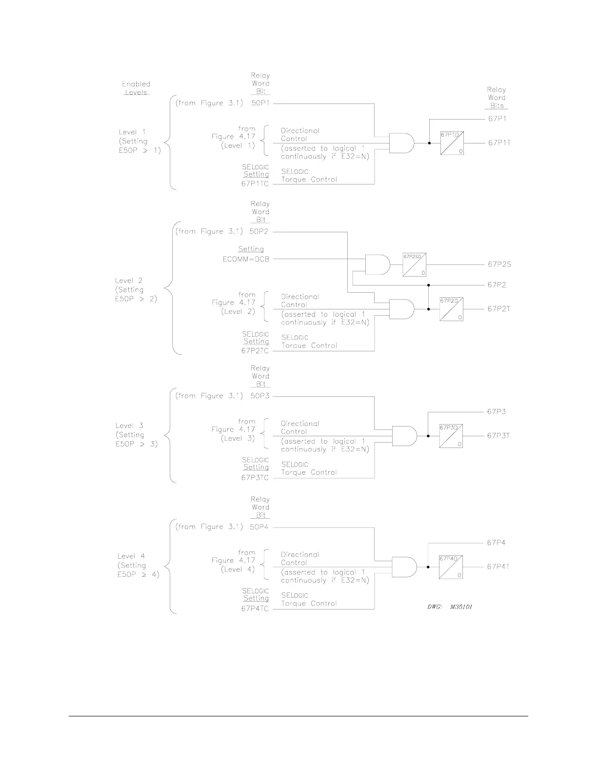
Phase Instantaneous/Definite-Time Overcurrent Elements
71
Settings Ranges
71
Accuracy
71
Pickup Operation
73
Directional Control Option
75
Torque Control
75
Combined Single-Phase Instantaneous Overcurrent Elements
76
Pickup and Reset Time Curves
76
Phase-to-Phase Instantaneous Overcurrent Elements
77
Setting Range
78
Accuracy
78
Pickup Operation
78
Pickup and Reset Time Curves
78
Neutral Ground Instantaneous/Definite-Time Overcurrent Elements
78
Settings Ranges
81
Accuracy
81
Pickup and Reset Time Curves
81
Residual Ground Instantaneous/Definite-Time Overcurrent Elements
82
Settings Ranges
82
Accuracy
82
Pickup and Reset Time Curves
82
Negative-Sequence Instantaneous/Definite-Time Overcurrent Elements
84
Settings Ranges
84
Accuracy
86
Pickup and Reset Time Curves
86
Time-Overcurrent Elements
86
Phase Time-Overcurrent Elements
86
Settings Ranges
86
Accuracy
89
Logic Outputs (51P1T element example)
89
Torque Control Switch Operation (51P1T element example)
89
Torque Control Switch Closed
89
Torque Control Switch Open
90
Control of Logic Point TCP1
90
Directional Control Option
90
Torque Control
91
Reset Timing Details (51P1T element example)
91
Setting 51P1RS = Y
92
Setting 51P1RS = N
92
Neutral Ground Time-Overcurrent Elements
92
Settings Ranges
94
Accuracy
94
Residual Ground Time-Overcurrent Elements
95
Settings Ranges
96
Accuracy
96
Negative-Sequence Time-Overcurrent Element
97
Settings Ranges
98
Accuracy
98
Voltage Elements
99
Voltage Values
99
Voltage Element Settings
99
Accuracy
103
Voltage Element Operation
103
Undervoltage Element Operation Example
103
Overvoltage Element Operation Example
104
Voltage Elements Used in POTT Logic
104
Synchronism Check Elements
104
Voltage Input VS Connected Phase-to-Phase or Beyond Delta-Wye Transformer
105
Synchronism Check Elements Settings
105
Setting SYNCP
105
Accuracy
106
Synchronism Check Elements Voltage Inputs
108
System Frequencies Determined from Voltages VA and VS
108
System Rotation Can Affect Setting SYNCP
108
Synchronism Check Elements Operation
109
Voltage Window
109
Other Uses for Voltage Window Elements
109
Block Synchronism Check Conditions
109
Slip Frequency Calculator
110
Angle Difference Calculator
110
Voltages VP and VS are “Static”
110
Voltages VP and VS are “Slipping”
111
Angle Difference Example (Voltages Vp and Vs are “Slipping”)
113
Synchronism Check Element Outputs
114
Voltages VP and VS are “Static” or Setting TCLOSD = 0.00
114
Voltages VP and VS are “Slipping” and Setting TCLOSD ( 0.00
114
Synchronism Check Applications for Automatic Reclosing and Manual Closing
115
Frequency Elements
116
Frequency Element Settings
116
Accuracy
118
Create Over- and Underfrequency Elements
118
Overfrequency Element
119
Underfrequency Element
119
Frequency Element Operation
119
Overfrequency Element Operation
119
Underfrequency Element Operation
120
Frequency Element Voltage Control
120
Other Uses for Undervoltage Element 27B81
120
Frequency Element Uses
120
Underfrequency Loadshedding
120
Voltage Sag, Swell, and Interruption Elements (Available in Firmware Version 7)
121
Voltage Sag Elements
121
Voltage Swell Elements
122
Voltage Interruption Elements
122
Voltage Sag, Swell, and Interruption Elements Settings
123
Positive-Sequence Reference Voltage, Vbase
123
Vbase Thermal Element Block
123
Vbase Initialization
124
Vbase Tracking Range
125
SSI Reset command
125
Power Elements (Available in Firmware Version 7)
125
Power Elements Settings
126
Accuracy
126
Power Elements Logic Operation
127
Power Elements Application – VAR Control for a Capacitor Bank
129
Section 4: Loss-of-Potential, Load Encroachment, and Directional Element Logic
133
LOSS-OF-POTENTIAL, LOAD ENCROACH˜MENT, AND DIRECTIONAL ELEMENT LOGIC
135
Loss-of-Potential Logic
135
Setting ELOP = Y or Y1
136
Setting ELOP = Y
136
Setting ELOP = N
136
Load-Encroachment Logic
137
Settings Ranges
138
Load-Encroachment Setting Example
138
Convert Maximum Loads to Equivalent Secondary Impedances
139
Convert Power Factors to Equivalent Load Angles
139
Apply Load-Encroachment Logic to a Phase Time-Overcurrent
139
Use SEL-321 Relay Application Guide for the SEL-351S Relay
141
Directional Control for Neutral Ground and Residual Ground Overcurrent Elements
141
Internal Enables
143
Best Choice Ground Directional Logic
143
Directional Elements
143
Directional Element Routing
143
Loss-of-Potential
144
Direction Forward/Reverse Logic
144
Directional Control for Negative-Sequence and Phase Overcurrent Elements
151
Internal Enables
152
Directional Elements
152
Directional Element Routing
153
Loss-of-Potential
153
Direction Forward/Reverse Logic
153
Directional Control Settings
160
Settings Made Automatically
160
Settings
161
DIR1 – Level 1 Overcurrent Element Direction Setting
161
DIR2 – Level 2 Overcurrent Element Direction Setting
161
DIR3 – Level 3 Overcurrent Element Direction Setting
161
DIR4 – Level 4 Overcurrent Element Direction Setting
161
ORDER – Ground Directional Element Priority Setting
162
50P32P – Phase Directional Element Three-Phase Current Pickup
163
Z2F – Forward Directional Z2 Threshold
163
Z2R – Reverse Directional Z2 Threshold
163
Z2F and Z2R Set Automatically
163
50QFP – Forward Directional Negative-Sequence Current Pickup
164
50QRP – Reverse Directional Negative-Sequence Current Pickup
164
50QFP and 50QRP Set Automatically
164
a2 – Positive-Sequence Current Restraint Factor, I2/I1
164
a2 Set Automatically
164
k2 – Zero-Sequence Current Restraint Factor, I2/I0
165
k2 Set Automatically
165
50GFP – Forward Directional Residual Ground Current Pickup
166
50GRP – Reverse Directional Residual Ground Current Pickup
166
50GFP and 50GRP Set Automatically
166
a0 – Positive-Sequence Current Restraint Factor, I0/I1
166
a0 Set Automatically
167
Z0F – Forward Directional Z0 Threshold
167
Z0R – Reverse Directional Z0 Threshold
167
Z0F and Z0R Set Automatically
167
E32IV – SELogic Control Equation Enable
167
Directional Control Provided by Torque Control Settings
168
Section 5: Trip and Target Logic
171
TRIP AND TARGET LOGIC
175
Trip Logic
175
Set Trip
177
Unlatch Trip
178
Other Applications for the Target Reset Function
178
Factory Settings Example (Using Setting TR)
178
Set Trip
178
Unlatch Trip
179
Additional Settings Examples
179
Unlatch Trip with 52a Circuit Breaker Auxiliary Contact
180
Unlatch Trip With 52b Circuit Breaker Auxiliary Contact
180
Program an Output Contact for Tripping
180
TRIP Used in Other Settings
180
Change the Trip Settings - Check Other Settings
181
Switch-Onto-Fault (SOTF) Trip Logic
182
Three-Pole Open Logic
183
Determining Three-Pole Open Condition Without Circuit Breaker Auxiliary Contact
184
Circuit Breaker Operated Switch-Onto-Fault Logic
184
Close Bus Operated Switch-Onto-Fault Logic
184
Switch-Onto-Fault Logic Output (SOTFE)
185
Switch-Onto-Fault Trip Logic Trip Setting (TRSOTF)
185
Communications-Assisted Trip Logic – General Overview
186
Enable Setting ECOMM
186
Trip Setting TRCOMM
187
Trip Settings TRSOTF and TR
187
Trip Setting DTT
188
Use Existing SEL˚321 Relay Application Guides for the SEL˚351S€Relay
188
Optoisolated Input Settings Differences Between the SEL˚321 and SEL˚351S€Relays
188
Trip Settings Differences Between the SEL˚321 and SEL˚351S Relays
189
Permissive Overreaching Transfer Trip (POTT) Logic
189
Use Existing SEL˚321 Relay POTT Application Guide for the SEL˚351S Relay
189
External Inputs
189
PT1 – Received Permissive Trip Signal(s)
190
Timer Settings
190
Z3RBD – Zone (Level) 3 Reverse Block Delay
190
EBLKD – Echo Block Delay
190
ETDPU – Echo Time Delay Pickup
191
EDURD – Echo Duration
191
Logic Outputs
191
Z3RB – Zone (Level) 3 Reverse Block
191
ECTT – Echo Conversion to Trip
191
KEY – Key Permissive Trip
191
EKEY – Echo Key Permissive Trip
191
Variations for Permissive Underreaching Transfer Trip (PUTT) Scheme
193
Installation Variations
193
Directional Comparison Unblocking (DCUB) Logic
194
Use Existing SEL˚321 Relay DCUB Application Guide for the SEL˚351S Relay
195
External Inputs
195
PT1, PT2 – Received Permissive Trip Signal(s)
195
LOG1, LOG2 – Loss-of-Guard Signal(s)
195
Timer Settings
196
GARD1D – Guard-Present Delay
196
UBDURD – DCUB Disable Delay
196
UBEND – DCUB Duration Delay
196
Logic Outputs
196
UBB1, UBB2 – Unblocking Block Output(s)
196
PTRX1, PTRX2 – Permissive Trip Receive Outputs
198
Installation Variations
198
Directional Comparison Blocking (DCB) Logic
199
Use Existing SEL˚321 Relay DCB Application Guide for the SEL˚351S Relay
199
External Inputs
199
BT – Received Block Trip Signal(s)
200
Timer Settings
200
Z3XPU – Zone (Level) 3 Reverse Pickup Time Delay
200
Z3XD – Zone (Level) 3 Reverse Dropout Extension
200
BTXD – Block Trip Receive Extension
200
67P2SD, 67N2SD, 67G2SD, 67Q2SD – Level€2 Short Delay
200
Logic Outputs
200
DSTRT – Directional Carrier Start
201
NSTRT – Nondirectional Carrier Start
201
STOP – Stop Carrier
201
BTX – Block Trip Extension
201
Installation Variations
202
Front-Panel Target LEDs
204
Front-Panel Target LED Logic Details
206
Correlation between Trip Target LEDs and Trip Settings
207
LED12 (TRIP)
207
LED13 (INST)
207
LED14 (COMM) and LED15 (SOTF)
207
LED16 (50) and LED17 (51)
208
LED18 (81)
208
LED25 (G)
208
LED26 (N)
208
Change the Trip Settings – Change the Target LED Logic
208
RECLOSING STATE LEDs
209
Target Reset/Lamp Test Front-Panel Pushbutton
209
Other Applications for the Target Reset Function
209
SELogic Control Equation Setting FAULT
210
Section 6: Close and Reclose Logic
211
CLOSE AND RECLOSE LOGIC
213
Close Logic
213
Set Close
214
Unlatch Close
214
Factory Settings Example
215
Set Close
215
Unlatch Close
216
Defeat the Close Logic
217
Circuit Breaker Status
217
52A Used in Many Settings
218
Program an Output Contact for Closing
218
Reclose Supervision Logic
218
Settings and General Operation
221
For Most Applications (Top of Figure€6.5)
221
For A Few, Unique Applications (Bottom of Figure€6.5 and Figure€6.6)
221
Set Reclose Supervision Logic (Bottom of Figure€6.5)
222
Unlatch Reclose Supervision Logic (Bottom of Figure€6.5)
222
Factory Settings Example
223
Additional Settings Example 1
223
SEL˚351S(1) Relay
224
SEL˚351S(2) Relay
224
Other Setting Considerations for SEL˚351S(1) and SEL˚351S(2) Relays
224
Additional Settings Example 2
225
Reclosing Relay
225
Reclosing Relay States and General Operation
226
Lockout State
227
Reclosing Relay States and Settings/Setting Group Changes
227
Defeat the Reclosing Relay
228
Close Logic Can Still Operate When the Reclosing Relay is Defeated
228
Reclosing Relay Timer Settings
228
Open-Interval Timers
229
Determination of Number of Reclosures (Last Shot)
230
Observe Shot Counter Operation
230
Reset Timer
230
Monitoring Open-interval and Reset Timing
231
Reclosing Relay Shot Counter
231
Reclosing Relay SELogic Control Equation Settings Overview
232
Reclose Initiate and Reclose Initiate Supervision Settings (79RI and 79RIS, Respectively)
232
Factory Settings Example
232
Additional Settings Example
233
Other Settings Considerations
234
Drive-to-Lockout and Drive-to-Last Shot Settings (79DTL and 79DLS, Respectively)
234
Factory Settings Example
235
Additional Settings Example 1
236
Other Settings Considerations
236
Skip Shot and Stall Open-Interval Timing Settings (79SKP and 79STL, Respectively)
236
Factory Settings Example
237
Additional Settings Example 1
237
Additional Settings Example 2
238
Additional Settings Example 3
238
Other Settings Considerations
238
Block Reset Timing Setting (79BRS)
239
Factory Settings Example
239
Additional Settings Example 1
239
Additional Settings Example 2
240
Sequence Coordination Setting (79SEQ)
240
Factory Settings Example
240
Additional Settings Example 1
241
Additional Settings Example 2
243
Reclose Supervision Setting (79CLS)
244
Section 7: Inputs, Outputs, Timers, and Other Control Logic
245
INPUTS, OUTPUTS, TIMERS, AND OTHER CONTROL LOGIC
249
Optoisolated Inputs
249
Input Debounce Timers
251
Input Functions
251
Settings Examples
252
Input IN101
252
Input IN102
252
Local Control Switches
253
Local Control Switch Types
254
ON/OFF Switch
254
OFF/MOMENTARY Switch
254
ON/OFF/MOMENTARY Switch
255
Settings Examples
256
Additional Local Control Switch Application Ideas
257
Local Control Switch States Retained
257
Power Loss
257
Settings Change or Active Setting Group Change
258
Remote Control Switches
258
Remote Bit Application Ideas
259
Remote Bit States Not Retained When Power is Lost
259
Remote Bit States Retained When Settings Changed or Active Setting Group Changed
259
Details on the Remote Control Switch MOMENTARY Position
259
Latch Control Switches
260
Latch Control Switch Application Ideas
261
Reclosing Relay Enable/Disable Setting Example
261
Feedback Control
262
Rising Edge Operators
262
Use a Remote Bit Instead to Enable/Disable the Reclosing Relay
264
Latch Control Switch States Retained
264
Power Loss
264
Settings Change or Active Setting Group Change
265
Reset Latch Bits for Active Setting Group Change
265
Note: Make Latch Control Switch Settings With Care
266
Multiple Setting Groups
268
Active Setting Group Indication
268
Selecting the Active Setting Group
268
Operation of SELogic Control Equation Settings SS1 Through SS6
269
Operation of Serial Port GROUP Command and Front-Panel GROUP Pushbutton
269
Relay Disabled Momentarily During Active Setting Group Change
270
Active Setting Group Switching Example 1
270
Start Out in Setting Group 1
272
Switch to Setting Group 4
272
Switch Back to Setting Group 1
272
Active Setting Group Switching Example 2
273
Selector Switch Starts Out in Position 3
274
Selector Switch Switched to Position 5
275
Selector Switch Now Rests on Position REMOTE
275
Active Setting Group Retained
276
Power Loss
276
Settings Change
276
Note: Make Active Setting Group Switching Settings with Care
277
SELogic Control Equation Variables/Timers
277
Factory Settings Example
279
Additional Settings Example 1
279
Additional Settings Example 2
280
Timers Reset When Power is Lost, Settings are Changed, or Active Setting Group is Changed
280
Output Contacts
281
Factory Settings Example
281
Operation of Output Contacts for Different Output Contact Types
281
Output Contacts OUT101 Through OUT107
281
ALARM Output Contact
282
Rotating Default Display
284
Traditional Indicating Panel Lights
285
Reclosing Relay Status Indication
285
Circuit Breaker Status Indication
285
Traditional Indicating Panel Lights Replaced with Rotating Default Display
285
General Operation of Rotating Default Display Settings
286
Settings Examples
286
Reclosing Relay Status Indication
286
Reclosing Relay Enabled
287
Reclosing Relay Disabled
287
Circuit Breaker Status Indication
287
Circuit Breaker Closed
287
Circuit Breaker Open
288
Additional Settings Examples
288
Display Only One Message
288
Circuit Breaker Closed
288
Circuit Breaker Open
289
Continually Display a Message
289
Active Setting Group Switching Considerations
289
Setting Group 1 is the Active Setting Group
290
Reclosing Relay Enabled
290
Reclosing Relay Disabled
290
Switch to Setting Group 4 as the Active Setting Group
290
Additional Rotating Default Display Example
291
Displaying Time-Overcurrent Elements on the Rotating Default Display
291
Displaying Time-Overcurrent Elements Example
291
Displaying Metering Quantities on the Rotating Default Display
292
Displaying Metering Values Example
292
Displaying Breaker Monitor Output Information on the Rotating Default Display
293
Displaying Breaker Monitor Outputs Example
293
Section 8: Breaker Monitor, Metering, and Load Profile Functions
295
BREAKER MONITOR, METERING, AND LOAD PROFILE FUNCTIONS
297
Introduction
297
Breaker Monitor
297
Breaker Monitor Setting Example
300
Breaker Maintenance Curve Details
300
Operation of SELogic Control Equation Breaker Monitor Initiation Setting BKMON
302
Breaker Monitor Operation Example
303
0 Percent to 10 Percent Breaker Wear
303
10 Percent to 25 Percent Breaker Wear
303
25 Percent to 50 Percent Breaker Wear
303
50 Percent to 100 Percent Breaker Wear
303
Breaker Monitor Output
308
Example Applications
308
View or Reset Breaker Monitor Information
308
Via Serial Port
308
Via Front Panel
309
Determination of Relay Initiated Trips and Externally Initiated Trips
309
Factory Default Setting Example
309
Additional Example
309
Station DC Battery Monitor
310
DC Under- and Overvoltage Elements
311
Create Desired Logic for DC Under- and Overvoltage Alarming
311
DCLO < DCHI (Top of Figure€8.10)
312
DCLO > DCHI (Bottom of Figure€8.10)
313
Output Contact Type Considerations (“a” or “b”)
313
Additional Application
313
View Station DC Battery Voltage
314
Via Serial Port
314
Via Front Panel
314
Analyze Station DC Battery Voltage
314
Station DC Battery Voltage Dips During Circuit Breaker Tripping
314
Station DC Battery Voltage Dips During Circuit Breaker Closing
315
Station DC Battery Voltage Dips Anytime
315
Operation of Station DC Battery Monitor When AC Voltage is Powering the Relay
315
Demand Metering
316
Comparison of Thermal and Rolling Demand Meters
316
Thermal Demand Meter Response (EDEM = THM)
318
Rolling Demand Meter Response (EDEM = ROL)
318
Time = 0 Minutes
319
Time = 5 Minutes
319
Time = 10 Minutes
320
Time = 15 Minutes
320
Demand Meter Settings
320
Demand Current Logic Output Application – Raise Pickup for Unbalance Current
322
Residual Ground Demand Current Below Pickup GDEMP
323
Residual Ground Demand Current Goes Above Pickup GDEMP
323
Residual Ground Demand Current Goes Below Pickup GDEMP Again
323
View or Reset Demand Metering Information
324
Via Serial Port
324
Via Front Panel
324
Demand Metering Updating and Storage
324
Energy Metering
324
View or Reset Energy Metering Information
324
Via Serial Port
324
Via Front Panel
325
Energy Metering Updating and Storage
325
Maximum/Minimum Metering
325
View or Reset Maximum/Minimum Metering Information
325
Via Serial Port
325
Via Front Panel
325
Maximum/Minimum Metering Updating and Storage
325
Load Profile Report (Available in Firmware Versions 6 and 7)
326
Determining the size of the Load Profile Buffer
329
Clearing the Load Profile Buffer
329
Section 9: Setting the Relay
331
SETTING THE RELAY
333
Introduction
333
Settings Changes via the Front Panel
333
Settings Changes via the Serial Port
333
Time-Overcurrent Curves
335
Recloser Curves
336
Relay Word Bits (Used in SELOGIC Control Equations)
350
Relay Word Bits Comments
351
Settings Explanations
375
Identifier Labels
375
Current Transformer Ratios
375
Line Settings
376
Enable Settings
376
Neutral Ground Overcurrent Settings
377
Demand Metering Settings
377
Other System Parameters
377
Settings Sheets
377
Settings Sheet
379
Identifier Labels (See Settings Explanations in Section 9)
379
Current and Potential Transformer Ratios (See Settings Explanations in Section 9)
379
Line Settings (See Settings Explanations in Section 9)
379
Instantaneous/Definite-Time Overcurrent Enable Settings
379
Time-Overcurrent Enable Settings
379
Other Enable Settings
379
Phase Inst./Def.-Time Overcurrent Elements (See Figures 3.1, 3.2, and 3.3)
380
Phase Definite-Time Overcurrent Elements (See Figure 3.3)
380
Phase-to-Phase Instantaneous Overcurrent Elements (See Figure 3.7)
380
Neutral Ground Inst./Def.-Time Overcurrent Elements – Channel IN (See Figures 3.8 and 3.9)
381
Neutral Ground Definite-Time Overcurrent Elements (See Figure 3.8)
381
Residual Ground Inst./Def.-Time Overcurrent Elements (See Figures 3.10 and 3.11)
381
Residual Ground Definite-Time Overcurrent Elements (See Figure 3.10)
381
Negative-Sequence Inst./Def.-Time Overcurrent Elements (See Figures 3.12 and 3.13)*
382
Negative-Sequence Definite-Time Overcurrent Elements (See Figure 3.12)*
382
Phase Time-Overcurrent Element (See Figure 3.14 and 3.15)
382
Neutral Ground Time-Overcurrent Elements - Channel IN (See Figure 3.16 and Figure€3.17)
383
Residual Ground Time-Overcurrent Elements - Channel IN (See Figure 3.18 and Figure€3.19)
383
Negative-Sequence Time-Overcurrent Element (See Figure 3.20)*
384
Load-Encroachment Elements (See Figure 4.2)
384
Directional Elements (See Directional Control Settings in Section 4)
384
Voltage Elements (See Figures 3.21, 3.22, and 3.23)
385
Synchronism Check Elements (See Figures 3.24 and 3.25)
386
Frequency Element (See Figure 3.28)
386
Reclosing Relay (See Tables 6.2 and 6.3)
387
Switch-Onto-Fault (See Figure 5.3)
387
POTT Trip Scheme Settings (Also Used in DCUB Trip Schemes) (See Figure 5.6)
387
Additional DCUB Trip Scheme Settings (See Figure 5.10)
387
DCB Trip Scheme Settings (See Figure 5.14)
388
Demand Metering Settings (See Figures 8.11 and 8.13)
388
Other Settings
388
SELogic Control Equation Variable Timers (See Figures 7.24 and 7.25)
389
Power Elements (Available in Firmware Version 7; see Figure 3.33)
390
Voltage Sag/Swell/Interrupt (Available in Firmware Version 7; see Figures 3.29, 3.30, 3.31)
390
Trip Logic Equations (See Figure 5.1)
391
Communications-Assisted Trip Scheme Input Equations
391
Close Logic Equations (See Figure 6.1))
391
Reclosing Relay Equations (See Reclosing Relay in Section 6)
391
Latch Bits Set/Reset Equations (See Figure 7.12)
392
Torque Control Equations for Inst./Def.-Time Overcurrent Elements
393
Torque Control Equations for Time-Overcurrent Elements
393
SELogic Control Equation Variable Timer Input Equations (See Figures 7.24 and 7.25)
393
Output Contact Equations (See Figure 7.27)
394
Output Contact Equations - Extra I/O Board (See Figure€7.28)
394
Target and Operator Control LED Equations (see Table 5.1, and Figures 11.8 and 11.9)
394
Display Point Equations (See Rotating Default Display in Sections 7 and 11)
395
Setting Group Selection Equations (See Table 7.4)
396
Other Equations
396
Mirrored Bits™ Transmit Equations (Available in Firmware Versions 6 and Greater; see Appendix I)
396
Settings Group Change Delay (See Multiple Setting Groups in Section 7)
397
Power System Configuration and Date Format (See Settings Explanations in Section€9)
397
Front-Panel Display Operation (See Section 11)
397
Event Report Parameters (See Section 12)
397
Station DC Battery Monitor (See Figures 8.9 and 8.10)
397
Optoisolated Input Timers (See Figure 7.1)
397
Optoisolated Input Timers - Extra I/O Board (See Figure€7.2)
398
Breaker Monitor Settings (See Breaker Monitor in Section 8)
398
Trip Latch LEDs Settings (See Table 5.1)
398
Operator Control Time Delays (See Figures 11.12 and 11.13)
399
Local Bit Labels (See Tables 7.1 and 7.2)
401
Display Point Labels (See Rotating Default Display in Sections 7 and 11)
403
Reclosing Relay Labels (See Functions Unique to the Front-Panel Interface in Section€11)
404
Protocol Settings (See Below)
405
Communications Settings
405
Other Port Settings (See Below)
405
Section 10: Serial Port Communications and Commands
407
SERIAL PORT COMMUNICATIONS AND COMMANDS
409
Introduction
409
Port Connector and Communications Cables
409
IRIG-B
409
SEL˚351S to Computer
411
SEL˚351S to Modem
411
SEL˚351S to SEL˚PRTU
412
SEL˚351S to SEL˚2020, SEL-2030, or SEL-2100
412
SEL-351S to SEL-DTA2
412
Communications Protocol
413
Hardware Protocol
413
Software Protocols
413
SEL ASCII Protocol
414
SEL Distributed Port Switch Protocol (LMD)
415
SEL Fast Meter Protocol
415
SEL Compressed ASCII Protocol
415
Distributed Network Protocol (DNP) 3.00
415
Mirrored Bits Communications
415
Serial Port Automatic Messages
415
Serial Port Access Levels
416
Access Level 0
416
Access Level 1
417
Access Level B
417
Access Level 2
418
Command Summary
418
Command Explanations
420
Access Level 0 Commands
420
ACC, BAC, and 2AC Commands (go to Access Level 1, B, or 2)
420
Password Requirements
420
Access Level Attempt (Password Required)
421
Access Level Attempt (Password Not Required)
421
Access Level 1 Commands
422
BRE Command (Breaker Monitor Data)
422
COMM Command (Communication Data - Available in Firmware Versions 6 and 7)
422
DAT Command (View/Change Date)
423
EVE Command (Event Reports)
424
GRO Command (Display Active Setting Group Number)
424
HIS Command (Event Summaries/History)
424
IRI Command (Synchronize to IRIG-B Time Code)
426
LDP Command (Load Profile Report - Available in Firmware Versions 6 and 7)
426
MET Command (Metering Data)
426
MET k – Instantaneous Metering
427
MET X k – Extended Instantaneous Metering
428
MET D – Demand Metering
429
MET E – Energy Metering
430
MET M – Maximum/Minimum Metering
431
QUI Command (Quit Access Level)
432
SER Command (Sequential Events Recorder Report)
432
SHO Command (Show/View Settings)
432
SSI Command (Voltage Sag/Swell/Interruption Report - Available in Firmware Version 7)
438
STA Command (Relay Self-Test Status)
438
STA Command Row and Column Definitions
439
TAR Command (Display Relay Element Status)
440
TIM Command (View/Change Time)
441
TRI Command (Trigger Event Report)
441
Access Level B Commands
442
BRE n Command (Preload/Reset Breaker Wear)
442
CLO Command (Close Breaker)
443
GRO n Command (Change Active Setting Group)
443
OPE Command (Open Breaker)
444
PUL Command (Pulse Output Contact)
444
Access Level 2 Commands
445
CON Command (Control Remote Bit)
445
COP m n Command (Copy Setting Group)
445
LOO Command (Loop Back - Available in Firmware Versions 6 and 7)
446
PAS Command (View/Change Passwords)
447
SET Command (Change Settings)
448
VER Command (Show Relay Configuration and Firmware Version)
448
SEL-351S Relay Command Summary
449
Section 11: Front-Panel Interface
453
FRONT-PANEL INTERFACE
455
Introduction
455
Front-Panel Pushbutton Operation
455
Overview
455
Primary Functions
455
Front-Panel Password Security
456
Secondary Functions
457
Functions Unique to the Front-Panel Interface
459
Reclosing Relay Shot Counter Screen
459
Reclosing Relay Shot Counter Screen Operation (With Example Settings)
460
Local Control
461
View Local Control (Example Settings)
462
Operate Local Control (With Factory Settings)
462
Local Control State Retained When Relay Deenergized
464
Rotating Default Display
465
Scroll Lock Control of Front-Panel LCD
467
Stop Scrolling (Lock)
467
Restart Scrolling (Unlock)
467
Single Step
467
Exit
468
Cancel
468
Front-Panel Neutral / Ground Current Display
468
Additional Rotating Default Display Example
468
Operator Controls
468
Detailed Operator Control Pushbutton Output
474
GROUND ENABLED Operator Control Pushbutton Output
474
Other Operator Control Pushbutton Outputs Operate Similarly to GROUND ENABLED
475
LOCK Operator Control Pushbutton Output
475
TRIP and CLOSE Operator Control Pushbutton Outputs (0351Sxxx3 Models Only)
476
AUX 3 and AUX 4 Operator Control Pushbutton Outputs (0351Sxxx5 Models Only)
478
Corresponding Operator Control LEDs and Logic
479
GROUND ENABLED Operator Control
479
RECLOSE ENABLED and HOT LINE TAG Operator Controls
480
REMOTE ENABLED Operator Control
481
Example Application for the REMOTE ENABLED Operator Control
481
AUX 1 and AUX 2 Operator Controls
482
AUX 3 and AUX 4 Operator Controls (0351Sxxx5 Models Only)
483
ALTERNATE SETTINGS Operator Control
483
LOCK Operator Control
484
Section 12: Standard Event Reports, Sag/Swell/Interruption Report, and SER
487
STANDARD EVENT REPORTS, SAG/SWELL/ INTERRUPTION REPORT, AND SER
489
Introduction
489
Standard 15/30-Cycle Event Reports
490
Event Report Length (Settings LER and PRE)
490
Standard Event Report Triggering
490
Relay Word Bit TRIP
490
Programmable SELogic Control Equation Setting ER
491
TRI (Trigger Event Report) and PUL (Pulse Output Contact) Commands
491
Standard Event Report Summary
492
Event Type
492
Fault Location
493
Targets
493
Currents
493
Retrieving Full-Length Standard Event Reports
494
Compressed ASCII Event Reports
495
Filtered and Unfiltered Event Reports
495
Clearing Standard Event Report Buffer
495
Standard Event Report Column Definitions
496
Current, Voltage, and Frequency Columns
496
Output, Input, and Protection, and Control Columns
496
SER Report
509
SER Triggering
509
Making SER Trigger Settings
510
Make SER Settings With Care
510
Retrieving SER Reports
510
Clearing SER Report
511
Example Standard 15-Cycle Event Report
512
Example SER Report
517
Sag/Swell/Interruption (SSI) Report (Available in Firmware Version€7)
519
SSI Triggering and Recording
519
SSI Report Entries
519
SSI Recorder Operation: Overview
520
SSI Recorder Operation: Detailed Description
521
SSI Report Memory Details
522
Retrieving the SSI Report
522
Clearing the SSI Report
524
Triggering the SSI Recorder
524
Resetting the SSI Recorder Logic
525
Sample SSI Report
526
Section 13: Testing and Troubleshooting
527
TESTING AND TROUBLESHOOTING
529
Introduction
529
Testing Philosophy
529
Acceptance Testing
529
Commissioning Testing
529
Maintenance Testing
530
Testing Methods and Tools
531
Test Features Provided by the Relay
531
Low-Level Test Interface
531
Sensitive Earth Fault (SEF) Channel IN (0.05 A Nominal)
532
Test Methods
532
Testing Via Front-Panel Indicators
533
Testing Via Output Contacts
533
Testing Via Sequential Events Recorder
533
Relay Self-Tests
534
Relay Troubleshooting
536
Inspection Procedure
536
Troubleshooting Procedure
536
All Front-Panel LEDs Dark
536
Cannot See Characters on Relay LCD Screen
537
Relay Does Not Respond to Commands From Device Connected to Serial Port
537
Relay Does Not Respond to Faults
537
Relay Calibration
537
Factory Assistance
537
Section 14: Appendices
539
APPENDIX A: FIRMWARE VERSIONS
543
APPENDIX B: FIRMWARE UPGRADE INSTRUCTIONS
547
Firmware (Flash) Upgrade Instructions
547
Important Note Regarding Settings
547
Required Equipment
547
Upgrade Procedure
547
APPENDIX C: SEL DISTRIBUTED PORT SWITCH PROTOCOL
553
Settings
553
Operation
553
APPENDIX D: CONFIGURATION, FAST METER, AND FAST OPERATE COMMANDS
555
Introduction
555
Message Lists
555
Binary Message List
555
ASCII Configuration Message List
555
Message Definitions
556
A5C0 Relay Definition Block
556
A5C1 Fast Meter Configuration Block
556
A5D1 Fast Meter Data Block
558
A5C2/A5C3 Demand/Peak Demand Fast Meter Configuration Messages
558
A5D2/A5D3 Demand/Peak Demand Fast Meter Message
560
A5B9 Fast Meter Status Acknowledge Message
561
A5CE Fast Operate Configuration Block
561
A5E0 Fast Operate Remote Bit Control
562
A5E3 Fast Operate Breaker Control
563
A5CD Fast Operate Reset Definition Block
564
A5ED Fast Operate Reset Command
564
ID Message
564
DNA Message
565
BNA Message
566
SNS Message
567
APPENDIX E: COMPRESSED ASCII COMMANDS
569
Introduction
569
CASCII Command – General Format
569
CASCII Command – SEL˚351S
570
CSTATUS Command – SEL˚351S
572
CHISTORY Command – SEL˚351S
572
CEVENT Command – SEL˚351S
573
APPENDIX F: SETTING NEGATIVE-SEQUENCE OVERCURRENT ELEMENTS
577
Setting Negative-Sequence Definite-Time Overcurrent Elements
577
Setting Negative-Sequence Time-Overcurrent Elements
577
Coordinating Negative-Sequence Overcurrent Elements
578
Coordination Guidelines
579
Coordination Example
579
Traditional Phase Coordination
580
Apply the Feeder Relay Negative-Sequence Overcurrent Element (Guidelines€1€to€3)
580
Convert “Equivalent” Phase Overcurrent Element Settings to Negative-Sequence€Overcurrent Element Settings (Guideline 4)
581
Negative-Sequence Overcurrent Element Applied at a Distribution Bus (Guideline 5)
582
Ground Coordination Concerns
583
Other Negative-Sequence Overcurrent Element References
583
APPENDIX G: SETTING SELogic® CONTROL EQUATIONS
585
Relay Word Bits
585
Relay Word Bit Operation Example – Phase Time-Overcurrent Element 51P1T
585
Phase Time-Overcurrent Element 51P1T Pickup Indication
585
Phase Time-Overcurrent Element 51P1T Time-Out Indication
586
Phase Time-Overcurrent Element 51P1T Reset Indication
586
Relay Word Bit Application Examples – Phase Time-Overcurrent Element 51P1T
586
Other Relay Word Bits
586
SELogic Control Equations
587
SELogic Control Equation Operators
587
SELogic Control Equation Parentheses Operator ( )
588
SELogic Control Equation NOT Operator !
588
Example of NOT Operator ! Applied to Single Element
588
Example of NOT Operator ! Applied to Multiple Elements (Within Parentheses)
589
SELogic Control Equation Rising Edge Operator /
589
SELogic Control Equation Falling Edge Operator \
591
SELogic Control Equation Operation Example – Tripping
591
Analysis of SELogic Control Equation Trip Setting TR
592
Set an Output Contact for Tripping
593
All SELogic Control Equations Must Be Set
593
Set SELogic Control Equations Directly to 1 or 0
593
Set SELogic Control Equations Directly to 1 or 0 – Example
594
SELogic Control Equation Limitations
594
Processing Order and Processing Interval
595
APPENDIX H: DISTRIBUTED NETWORK PROTOCOL (DNP) 3.00
599
Overview
599
Configuration
599
Standard Mode DNP Operation
599
Extended Mode DNP Operation
600
EIA-232 Physical Layer Operation
600
Data-Link Operation
601
Data Access Method
601
Device Profile
603
Object Table
605
Data Map
608
Relay Summary Event Data
613
Point Remapping
614
APPENDIX I: Mirrored Bits™ COMMUNICATIONS (IN FIRMWARE VERSIONS 6 AND 7)
619
Overview
619
Operation
620
Message Transmission
620
Message Decoding and Integrity Checks
620
Synchronization
621
Loop-Back Testing
621
Channel Monitoring
621
Mirrored Bits Protocol for the Pulsar 9600 Baud Modem
622
Settings
622
APPENDIX J: SEL-5030 acSELerator®
627
Introduction
627
acSELerator System Requirements
627
Installation
628
Starting acSELerator
628
SEL-351S Relay Command Summary
629
SEL-351S Relay Command Summary
633
Related product manuals
SEL-351
614 pages
SEL-351R
620 pages
SEL-351-5
696 pages
SEL-351-6
696 pages
SEL-351-7
696 pages
SEL-352-1
444 pages
SEL-321
396 pages
SEL-300G
714 pages
SEL-311C
748 pages
SEL-387E
578 pages
SEL-321-1
396 pages
SEL-787-3
32 pages