Do you have a question about the Schwinn 20 Series Bike and is the answer not in the manual?
| Resistance | Magnetic |
|---|---|
| Resistance Levels | 8 |
| Display | LCD |
| Seat | Padded, Adjustable |
| Drive System | Belt |
| Pedals | Standard |
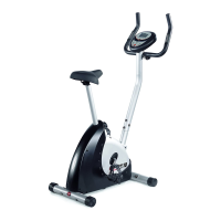
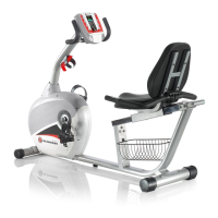
| Type | Upright |
| Heart Rate Monitor | Grip |
| Display Metrics | Time, Speed, Distance, Calories |
| Weight Capacity | 275 lbs (125 kg) |
| Dimensions | 39" L x 20" W x 48" H (99 x 51 x 122 cm) |
Outlines essential safety guidelines before and during equipment use, including warnings for children, medical consultation, and proper operation.
Provides fundamental tips to simplify the assembly process, such as gathering parts and understanding tightening rules.
Attaches the front stabilizer to the main frame using carriage bolts, arc washers, and acorn nuts.
Slides the saddle support frame onto the rail tube, ensuring wires pass through the frame without pinching.
Connects the rail tube assembly to the main frame using hex screws and flat washers, securing pulse wires.
Attaches the rear stabilizer bar to the rail tube assembly using hex screws and flat washers, ensuring correct orientation.
Attaches the handlebar to the saddle support frame and connects the handlebar wire connector to the pulse wire.
Installs the saddle and back cushion onto the saddle support frame using Phillips screws, allowing for height adjustment.
Feeds console wires through the front post, mounts the post to the main frame, and connects console wires.
Inserts the adjustment handle into the handle mount and tightens the screw, removing any protective ties.
Installs the left and right pedals onto their respective cranks, noting the left pedal's reverse thread, and inserts console batteries.
Ensures all hardware is tightened and reviews machine warnings and owner's manual sections for safe operation.