beam; the RED LIGHT, located in the front of the
P.C.BOARD, will glow immediately.
After approximately 6 seconds the ice maker
resume its operation with the immediate glowing
of the FOURTH YELLOW LIGHT indicating UNIT
IN OPERATION and the extinguishing of the
“BIN FULL” YELLOW LIGHT.
NOTE. The ICE LEVEL CONTROL
(INFRARED SYSTEM) is independent of the
temperature however, the reliability of its
detection can be affected by external light
radiations or by any sort of dirt and scale
sediment which may deposit directly on the
light source and on the receiver.To prevent
any possible ice maker malfunction, due to
negative affection of the light detector, it is
advisable to locate the unit where it is not
reached by any direct light beam or light
radiation, also it is recommended to keep the
bin door constantly closed and to follow the
instructions for the periodical cleaning of the
light sensor elements as detailed in the
MAINTENANCE AND CLEANING
PROCEDURES.
K. Remove, if fitted, the refrigerant service
gauges and re-fit the unit service panels
previously removed.
L. Instruct the owner/user on the general
operation of the ice machine and about the
cleaning and care it requires.
Page 17
H. Check, during the defrost cycle, that the
incoming water flows correctly into the sump
reservoir in order to refill it and that the surplus
overflows through the overflow drain tube.
I. Check the texture of ice cubes just released.
They have to be in the right shape with a small
depression of about 5-6 mm in their crown.
If not, wait for the completion of the second cycle
before performing any adjustment.
If required, the lenght of the timed freezing cycle
can be modified by changing the DIP SWITCH
keys setting as illustrated in OPERATING
PRINCIPLE.
If the ice cubes are shallow and cloudy, it is
possible that the ice maker runs short of water
during the freezing cycle second phase or, the
quality of the supplied water requires the use of
an appropriate water filter or conditioner.
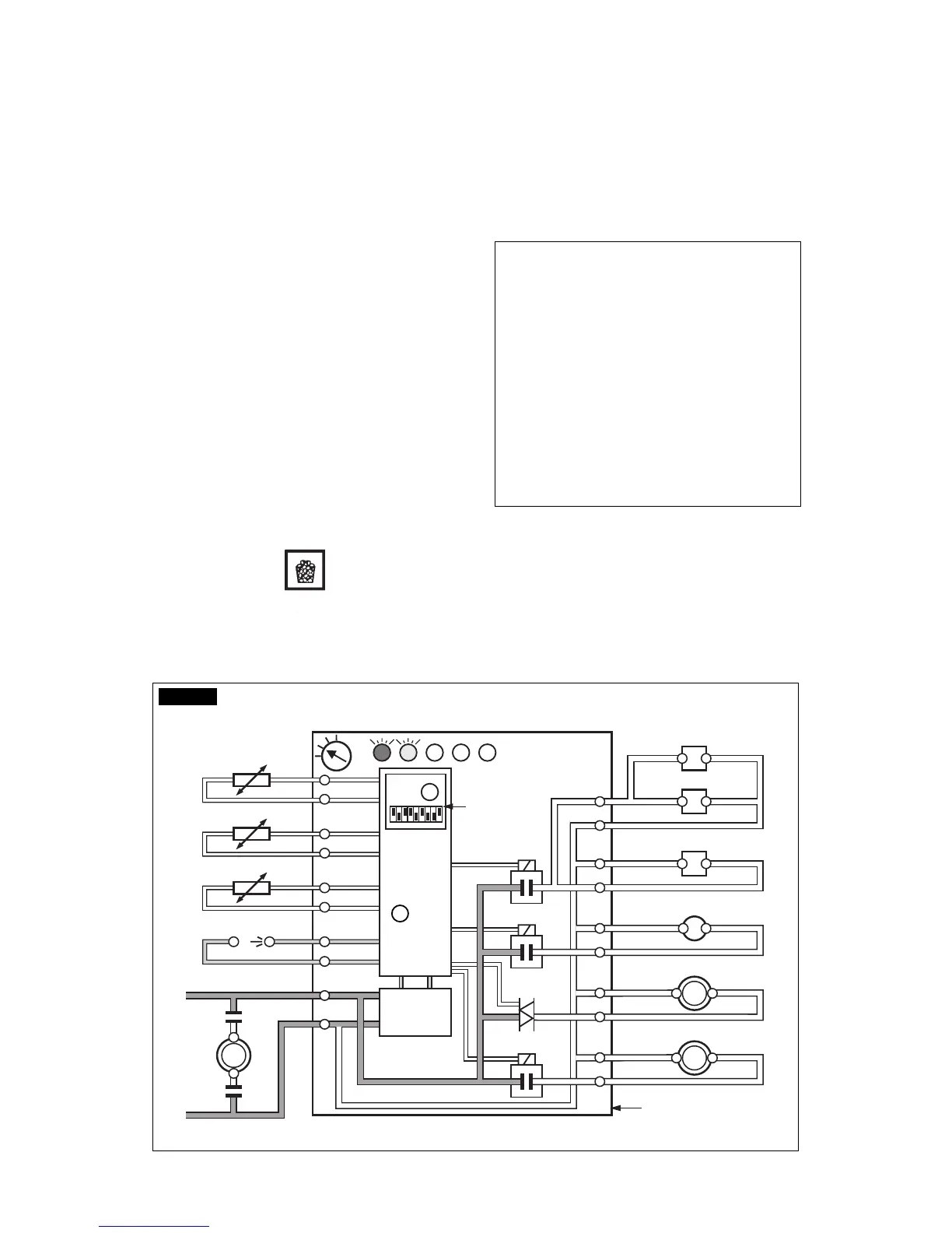
J. To be sure of the correct operation of ice
level control device, place one hand between its
sensing “eyes” to interrupt the light beam.
The RED LIGHT located in the front of the
P.C.BOARD goes immediately OFF, and after
60 seconds, the unit stops with the simultaneous
glowing of the 2nd YELLOW LIGHT to monitor
the BIN FULL situation (Fig.6).
Take the hand out from the ice level control
sensors to allow the resumption of the light
16
15
14
13
2
1
7
8
9
10
3
4
5
6
11
12
Rx Tx
WATER IN VALVE
HOT GAS VALVE
CONTACTOR COIL
FAN MOTOR
WATER PUMP
- EVAPORATOR
- AMBIENT
- CONDENSER
TEMPERATURE SENSORSBINCOMPRESSOR
TRANSF.
DATA
PROCESSOR
ELECTR.
TIMER
DIP
SWITCH
ELECTRONIC CARD
L
N
RELAYS
RELAY
TRIAC
WATER DRAIN VALVE
FIG. 6