Do you have a question about the Scotsman AF Series and is the answer not in the manual?
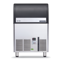
Specifications for the AF 80 model, including operating requirements and ice making capacity.
Detailed technical specifications for the AF80 model, including dimensions, electrical data, and capacity.
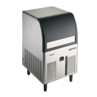
Specifications for the AF 100 model, including operating requirements and ice making capacity.
Detailed technical specifications for the AF100 model, including dimensions, electrical data, and capacity.
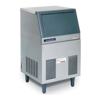
Specifications for the AF 200 model, including operating requirements and ice making capacity.
Detailed technical specifications for the AF 200 model, including dimensions, electrical data, and capacity.
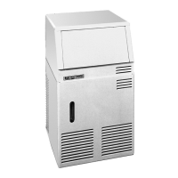
Specifications for the AF 20 model, including operating requirements and ice making capacity.
Detailed technical specifications for the AF20 model, including dimensions, electrical data, and capacity.
Specifications for the AF 30 model, including operating requirements and ice making capacity.
Detailed technical specifications for the AF30 model, including dimensions, electrical data, and capacity.
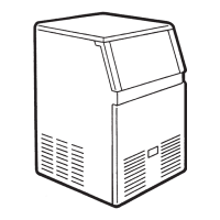
Overview of the manual and icemaker features.
Procedures for unpacking and checking the icemaker for damage.
Guidelines for placing and leveling the unit for optimal performance.
Instructions for making safe electrical connections to the icemaker.
Detailed instructions for connecting water supply and drain lines to the icemaker.
A checklist to ensure all installation steps are completed correctly before operation.
Visual guide and best practices for installing the icemaker.
Step-by-step procedure for starting the icemaker after installation.
How to check critical operations during the initial start-up phase.
How to test the ice level sensor and its impact on operation.
Final checks and instructions for the owner/user after initial setup.
Explains how water flows through the icemaker and forms ice.
Details the refrigeration cycle, including components and pressure points.
Explains refrigerant flow and temperature controls, including fan motor and condenser sensor.
Describes the gear motor, auger, and their operation.
Details refrigerant types, quantities, and metering devices.
Details discharge and suction pressures for different models at ambient temperature.
Describes the function and operation of the evaporator temperature sensor.
Explains the water level sensor system and its role in operation.
Details the condenser temperature sensor and its safety functions.
Describes the safety device for gear motor rotation and speed detection.
Explains the electronic ice bin level sensor and its function.
Details the function and components of the main control board (P.C. Board).
Explains the function of jumpers on the PC board for configuration.
Describes the float reservoir and its water level sensing components.
Details the construction and operation of the freezing cylinder.
Explains the function of the ice breaker and its bearing lubrication.
Describes the drive gear motor, its components, and lubrication.
Explains the operation of the fan motor in air-cooled models.
Describes the water regulating valve in water-cooled models.
Details the hermetic compressor and its role in the refrigeration system.
Instructions on how to adjust the water level in the evaporator.
Step-by-step guide to replace the evaporator temperature sensor.
Step-by-step guide to replace the condenser temperature sensor.
Instructions for replacing the ice level light control.
Guide for replacing the gear motor rotation and speed sensor.
Guide for replacing the reservoir water level sensor.
Step-by-step instructions for replacing the P.C. Board.
Instructions for removing and replacing the ice spout.
Detailed guide for replacing the auger, water seal, bearings, and coupling.
Instructions for replacing the gear motor assembly.
Guide for replacing the fan motor.
Step-by-step guide to replace the refrigerant drier.
Instructions for replacing the freezing cylinder.
Guide for replacing the air-cooled condenser.
Guide for replacing the water-cooled condenser.
Instructions for replacing the water regulating valve.
Detailed guide for replacing the compressor.
Instructions for replacing the gear motor magnetic sensor.
Wiring diagram and component legend for air and water-cooled models.
Troubleshooting steps for a unit that will not run or show any lights.
Troubleshooting steps for the bin full LED glowing without ice.
Troubleshooting steps for the water yellow LED indicator.
Troubleshooting steps for red alarm LED indicating high head pressure or ambient issues.
Troubleshooting steps for reverse rotation or slow gear motor issues.
Troubleshooting steps for combined yellow and red LED warnings.
Troubleshooting steps for intermittent compressor cycling, possibly due to low voltage.
Troubleshooting steps for low ice production issues.
Troubleshooting steps for producing wet ice.
Troubleshooting steps for when the machine runs but produces no ice.
Troubleshooting steps for water leaks in the system.
Troubleshooting steps for excessive noise or chattering.
Troubleshooting steps for gear motor noise.
Troubleshooting steps for issues related to water shortage.
General guidelines for maintenance and cleaning schedules.
Specific maintenance tasks for the icemaker, including checks and cleaning.
Detailed steps for cleaning the icemaker's water system.
Continuation of water system cleaning, including sanitizing.
| Dimensions | Varies by model |
|---|---|
| Power Usage | Varies by model |
| Refrigerant | R404A |
| Weight | Varies by model |
| Construction | Stainless Steel |
| Water Connection | Varies by model |
| Power Consumption | Varies by model |