Page 22
Page 22
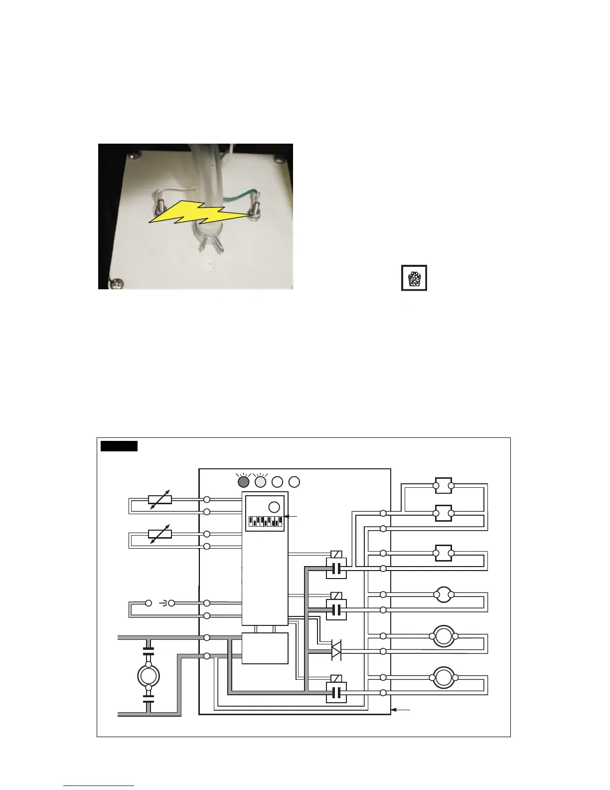
J. As soon as the water into the Sealed Water
Reservoir reaches the maximum level, the two
metal pins close the electrical contact through
the water, transmitting a low voltage current to
the Special Interface PC Board.
The Interface PC Board energises the Water
Drain Pump for 8 seconds pumping out most of
the water contained into the Sealed Water
Reservoir.
K. Check the texture of ice cubes just released.
They have to be in the right shape with a small
depression of about 5-6 mm in their crown.
If not, wait for the completion of the second cycle
before performing any adjustment.
If the ice cubes are shallow and cloudy, it is
possible that the ice maker runs short of water
during the freezing cycle second phase or, the
quality of the supplied water requires the use of
an appropriate water filter or conditioner.
L. To be sure of the correct operation of ice
level control device, place one hand between its
sensing “eyes” to interrupt the light beam.
The Bin Full YELLOW LED starts to blink, and
after 60 seconds, the unit stops with the
simultaneous glowing of the same LED to moni-
tor the BIN FULL situation (Fig.6).
Take the hand out from the ice level control
sensors to allow the resumption of the light
beam.
After approximately 6 seconds the ice maker
resume its operation with the immediate glowing
of the FIRST YELLOW LED indicating UNIT IN
OPERATION and the extinguishing of the “BIN
FULL” YELLOW LED.
16
15
14
13
2
1
7
8
9
10
3
4
5
6
11
12
Rx Tx
WATER IN VALVE
HOT GAS VALVE
CONTACTOR COIL
FAN MOTOR
WATER PUMP
- EVAPORATOR
- AMBIENT
- CONDENSER
TEMPERATURE SENSORSBINCOMPRESSOR
TRANSF.
DATA
PROCESSOR
ELECTR.
TIMER
DIP
SWITCH
ELECTRONIC CARD
L
N
RELAYS
RELAY
TRIAC
WATER DRAIN VALVE
FIG. 6