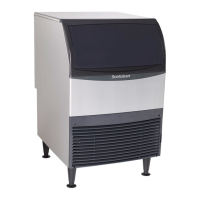
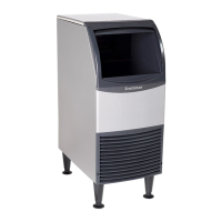
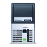
UC2024 and UC2724 Service Manual
November 2019
Page 2
To the owner or user: this manual is intended
to provide you and the maintenance or service
technician with the information needed to install,
startup, clean, maintain and repair this product.
Observe any caution or warning notices. They are
important and provide notice of potential hazards.
Keep this manual for future reference.
If additional technical information is needed, go to
Scotsman’s website, www.scotsman-ice.com.
Note: This is a commercial product. If service is
needed on a unit in a residence, warranty may be
limited. Use a commercial service company. Locate
one from the Scotsman website: www.Scotsman-ice.
com
Scotsman Ice Systems are designed and
manufactured with the highest regard for safety and
performance. They meet or exceed UL563, veried by
a nationally recognized safety authority such as UL or
ETL.
Introduction
Table of Contents
Specications ..................... Page 3
Cabinet Drawing ................... Page 4
Plan and Front Views ............... Page 5
Side and Back Views ............... Page 6
Placement ........................ Page 7
Installation ........................ Page 8
Initial Start Up ..................... Page 9
Use and Operation ................. Page 10
Ice Bridge Thickness Adjustment ...... Page 11
Indicator Light Reference ............ Page 12
Maintenance and Cleaning ........... Page 13
Condensers and Air Filter Cleaning ..... Page 15
The Systems ...................... Page 16
Selected Water Components .......... Page 17
Selected Electrical Components ....... Page 18
Selected Refrigeration Components .... Page 19
Controller ......................... Page 20
Ice Sensing Plate and Switch ......... Page 21
Test Mode ........................ Page 22
Thermistor Values .................. Page 23
Timed Cycles ...................... Page 24
Technical Information on UC2024 ..... Page 25
Technical Information on UC2724 ..... Page 26
Service Diagnosis .................. Page 27
Removal and Replacement ........... Page 29
Removal and Replacement ........... Page 30
Removal and Replacement ........... Page 31
Condenser Fan Motor ............... Page 32
Thermistors ....................... Page 33
Flap or Curtain Switch ............... Page 34
Hot Gas Valve and TXV .............. Page 35
Evaporator ........................ Page 36
Quick Reference ................... Page 37
Wiring Diagram UC2024 ............. Page 38
Wiring Diagram UC2724 ............. Page 39
Observe the Caution and
Warning notices. They are
indicators of important safety
information. Keep this manual
for future reference.
WARNING
CAUTION
 Loading...