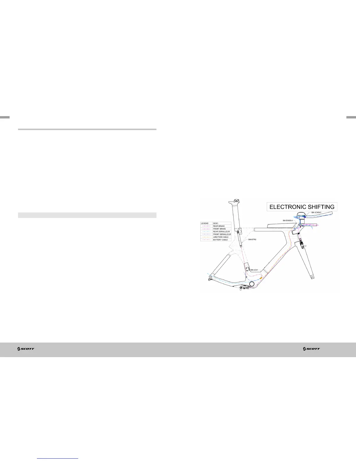
CABLE ROUTING: FOR ELECTRONIC SHIFTING
Front Derailleur (FD) & Rear Derailleur (RD) wires:
Route the COMMAND electric wire (approx. 1000mm) down from the headtube long
hole to the bottom bracket right hand housing.
Route the FD wire (approx. 200mm) down from the frame front derailleur exit hole
to the bottom bracket right hand housing.
Route the RD wire (approx. 500mm) down from the frame right dropout exit hole to
the bottom bracket right hand housing.
Route the BATTERY wire (approx. 600mm) down the seattube to the bottom
bracket right hand housing.
Plug all wires to the junction box SM-JC41, insert the box into the frame through
the bottom bracket right hand housing and make sure all wires will not disturb the
bottom bracket assembly.
Rear Brake (RB) Cable Housing:
IMPORTANT
To avoid any damage to the frame structure put a housing end plug at the end of
the housing.
Place the housing into the headtube long hole, push the housing until it touches
the rear end of the headtube (you may feel a resistance), orient the housing
up and push the housing again, it will then follow the headtube down and
continue its travel along the downtube, continue running the cable housing into
the frame.
Once the housing is visible from the bottom bracket opening, lead the housing to the
bottom bracket exit hole on the underside of the downtube in front of the bottom
bracket.
Pull the housing to leave approx. 100mm of cable housing outside the frame.
Front Brake (FB) Cable Housing:
refer to the Stem/Handlebar section.
Handlebar Command wiring:
route the wires into the Stem/Handlebar as described into the Stem/Handlebar
section.
Route the FD COMMAND & RD COMMAND wires through the headtube cap part (905).
Route the COMMAND wire through the headtube cap part (905), connect the wires
to the junction box SM-EW90-A, assemble the headtube cap part (905) as described
into the Headset/Stem body section and zip-tie the junction box SM-EW90-A to either
stem body or storage box.