CIRCUIT
DESCRIPTION
Design
Philosophy
on
430A and 410A
When using
a
high
gain
wide band
open loop
operational
amplifiers, it
is
possible
to
design
a
passive
network
providing a
negative
feedback to
control the
amplifier gain
and
frequency
response.
In
fact it
makes
easy
the
reproduction
and
repititivity
of the
wanted
results.
We
can
define
the gain
of
such an
amplifier as
follows.
Zm
o 'VW-
Vln
O
r
OP
AMP
3
PHONO IN R CH
C4
[PHONO AMPLtFIER USING OP AMP]
1)
Vo
=
-Vin-
2)
Rin
=
Zf
Zin
(Inverting Amp.)
OOUT
3)
Vo
=
Vin
•
1
+
Zin
c
—
R
in
^
Zf
Zl
Zino
•
Gopenloop
G
closedloop
(Non
Inverting)
Where
Ri
n
is
the
input
load
resistor. Z
m
is
the open loop
input
impedance
multiplied
by
open
loop
gain divided
by
closed
loop
gain.
Example:
If
open
loop gain
is
10,000
(i.e) 80dB)
and the
closed
loop gain is
100
(i.e
40dB).
For
an
amplifier
having
Zin
=
10K ohm,
the
equivalent
Zin
c
=
Rin
//
1000K
ohm.
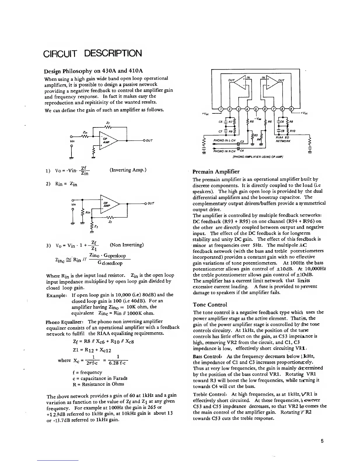
Phono
Equalizer:
The
phono non
inverting
amplifier
equalizer
consists
of an
operational
amplifier
with a
feedback
network
to
fullfil
the RIAA
equalizing
requirements.
Zf
=
R8
//
X
C
6
+
RlO
»
*c8
Zl
=Ri2
+
Xci2
1
1
where
X
c
=
2TTf-C
6.28 f-c
f
=
frequency
c
=
capacitance
in Farads
R
=
Resistance
in
Ohms
The
above
network
provides a
gain
of 60
at
1kHz
and
a gain
variation
as
function
to
the value
of
Zf
and
Z\ at
any
given
frequency.
For
example at
100Hz the
gain is 265
or
+12.9dB
referred
to
1kHz gain, at
10kHz
gain is
about
13
or
-l3.7dB
referred
to
1kHz
gain.
Premain
Amplifier
The
premain
amplifier is an
operational
amplifier built
by
discrete
components. It is
directly coupled to
the load (i.e
speakers).
The high gain open
loop
is
provided
by
the dual
differential
amplifiers and the boostrap
capacitor.
The
complementary
output
drivers/buffers provide a
symmetrical
output drive.
The amplifier is
controlled
by
multiple
feedback
networks:
DC
feedback (R93
+
R95) on
one channel (R94
+
R96)
on
the other are directly
coupled
between
output and
negative
input. The
effect of the DC
feedback
is
for longterm
stability and
unity DC gain.
The effect of
this
feedback
is
minor at
frequencies over
5Hz.
The
multipole
AC
feedback
network (with the bass and
treble
potentiometers
incorporated)
provides
a
constant gain
with no
effective
gain variations
of tone potentiometers. At
100Hz
the bass
potentiometer allows
gain control of ±10dB. At
10,000Hz
the
treble
potentiometer
allows
gain
control
of
±!OdB.
The amplifier has a
current limit network
that
limits
excessive current
loading.
A
fuse is provided
to
prevent
damage to
speakers if
the amplifier fails.
Tone Control
The tone control is a
negative feedback type whicli
uses the
power amplifier
stage
as
the active element. That
is,
the
gain of the power
amplifier stage
is
controlled
by
the
tone
controls circuitry. At
1kHz,
the position of
the tone
controls
has
little
effect
on
the
gain, as C5
3
impedance
is
high,
removing VR2
from the circuit, and CI,
C3
impedance
is low,
effectively short
circuiting VR1.
Bass Control: As
the frequency
decreases below
1
kHz,
the impedance
of CI and
C3
increases
proportionately.
Thus
at
very low
frequencies, the gain is
mainly
determined
by
the
position
of the bass
control
VR1.
Rotating
VR1
toward R3 will
boost the low
frequencies, while
turning
it
towards
C4
will
cut the bass.
Treble Control: At
high frequencies,
as at
1kHz,
\/Rl is
effectively short
circuited.
At
these
frequencies,
\
owever
C53 and C55
impdeance decreases, so that VR2
Is
comes the
the main
control of
the amplifier
gain. Rotating VR2
towards
C53
cuts
the treble response.
5
 Loading...