Power
Amplifier
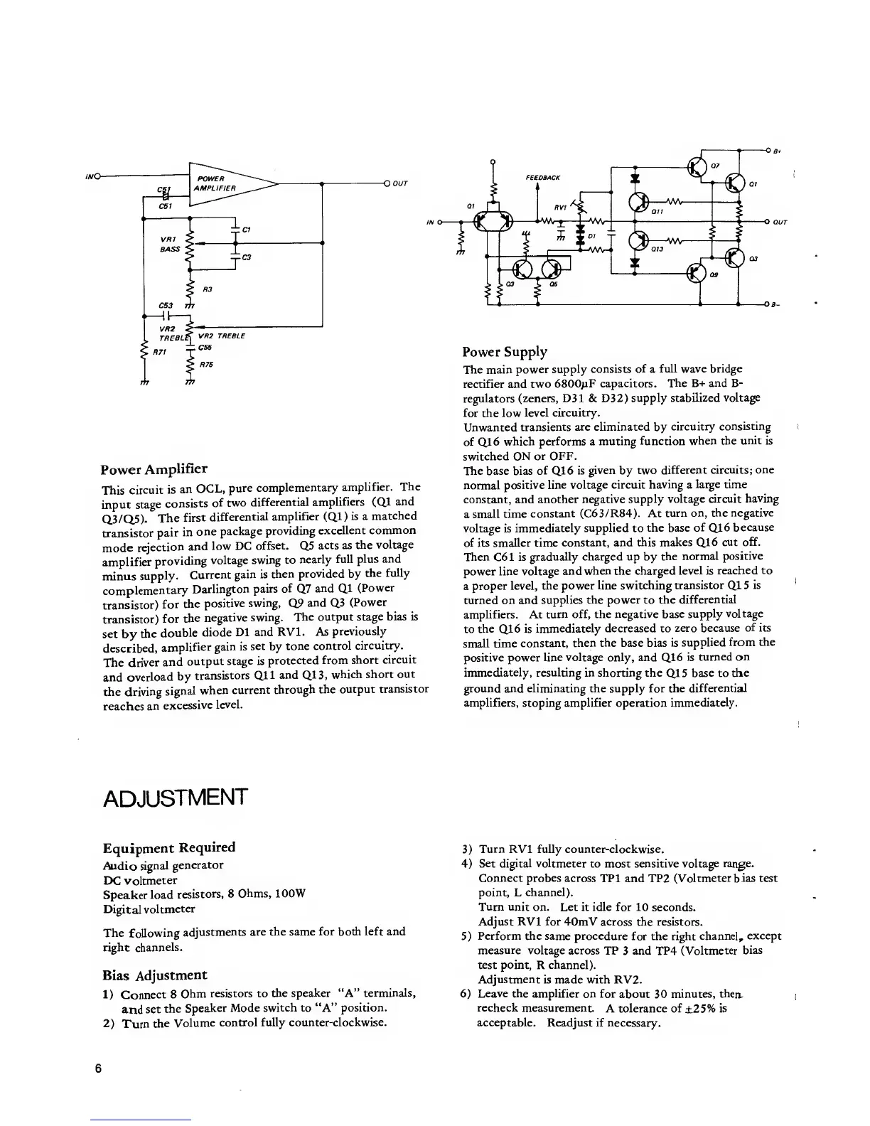
This
circuit
is
an
OCL,
pure
complementary
amplifier.
The
input stage
consists
of
two
differential
amplifiers
(Ql and
Q.3/Q.5).
The
first
differential
amplifier
(Ql
)
is a
matched
transistor
pair
in
one
package
providing
excellent
common
mode
rejection
and
low DC
offset.
Q5
acts as
the
voltage
amplifier
providing
voltage
swing to
nearly full
plus and
minus
supply.
Current
gain is
then
provided
by
the
fully
complementary
Darlington
pairs
of
Q7
and Ql
(Power
transistor)
for
the
positive
swing,
Q9
and
Q3
(Power
transistor)
for
the
negative
swing.
The output
stage
bias
is
set
by
the
double
diode
Dl and
RV1. As
previously
described,
amplifier
gain is
set
by
tone
control
circuitry.
The driver
and
output
stage is
protected
from
short
circuit
and
overload
by
transistors
Qll and
Q13,
which
short out
the driving
signal
when
current
through the
output
transistor
reaches
an
excessive
level.
Power
Supply
The main
power
supply consists
of
a
full wave bridge
rectifier and
two
6800uF
capacitors. The
B+
and
B-
regulators
(zeners, D31 & D32)
supply
stabilized voltage
for the low
level
circuitry.
Unwanted
transients are
eliminated
by
circuitry
consisting
of
Q16
which performs a
muting
function
when the
unit
is
switched ON
or OFF.
The base bias
of
Q16
is
given
by
two
different
circuits; one
normal
positive
line voltage circuit
having
a
large
time
constant, and
another
negative supply
voltage circuit
having
a
small time
constant
(C63/R84). At
turn on,
the negative
voltage is
immediately
supplied
to
the base
of
Q16
because
of its smaller time
constant, and
this makes
Q16
cut off.
Then
C61
is
gradually charged up by
the
normal
positive
power
line voltage and
when the charged
level
is
reached to
a
proper level,
the power
line
switching
transistor Ql 5
is
turned on
and
supplies the power to the
differential
amplifiers. At
turn off, the
negative
base
supply
voltage
to
the
Q16
is
immediately decreased to
zero because
of
its
small time
constant,
then
the
base bias
is
supplied
from the
positive power
line voltage only, and
Q16
is
turned on
immediately, resulting
in shorting the
Ql
5
base to
the
ground and eliminating the supply for the
differential
amplifiers,
stoping
amplifier
operation
immediately.
ADJUSTMENT
Equipment
Required
Audio
signal
generator
DC voltmeter
Speaker
load
resistors, 8
Ohms, 100W
Digital
voltmeter
The
following
adjustments
are the same
for
both
left and
right channels.
Bias
Adjustment
1)
Connect
8
Ohm
resistors to
the
speaker
"A"
terminals,
and
set
the
Speaker
Mode
switch to
"A"
position.
2)
Turn
the
Volume
control fully
counter-clockwise.
3)
Turn
RV1 fully counter-clockwise.
4)
Set digital voltmeter
to most sensitive voltage
range.
Connect probes across
TP1 and TP2
(Voltmeter bias test
point, L
channel).
Turn unit
on. Let it idle for 10 seconds.
Adjust RV1 for
40mV across the resistors.
5)
Perform the same procedure
for the right
channel,
except
measure
voltage across
TP 3 and TP4 (Voltmeter
bias
test point,
R
channel).
Adjustment
is made with RV2.
6)
Leave the amplifier
on for
about 30
minutes, then.
recheck
measurement.
A tolerance of +25% is
acceptable.
Readjust if necessary.
6
 Loading...