ENGLISHENGLISH
49 |
TREKKING AND TREKKING-PEDELEC | ORIGINAL OPERATING INSTRUCTIONS 2017ORIGINAL OPERATING INSTRUCTIONS 2017 | TREKKING AND TREKKING-PEDELEC
| 48
1
2
4
3
Adjustment of handlebar tilt and brake levers on SCOTT city, trekking,
urban and kids’ bikes
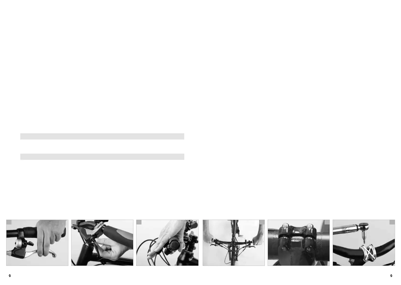
The handlebars are usually slightly bent at the ends. Set the handlebars to a
position in which your wrists are relaxed and not turned outwards too much (d).
Release the Allen bolt(s) at the bottom or front side of the stem.
Turn the handlebars to the desired position.
Make sure the handlebars are accurately centreed in the stem. Carefully retight-
en the bolt(s) with the torque wrench. Make sure the upper and lower clamping
slots of the stem are parallel and identical in width (e).
Tighten the bolts evenly and in a cross pattern (f), i.e. alternately and gradually,
to the lower value of the recommended torque values using a torque wrench.
Once clamped in the stem try rotating the handlebars and tighten the bolt a
little more, if necessary. Use a torque wrench and never exceed the maximum
torque values! You find them directly on the components and/or in the manuals
of the component manufacturers on this SCOTT info CD. If the handlebars are
not tight with the prescribed torque value, use carbon assembly paste.
After adjusting the handlebars you need to adjust the brake lever/shifter units.
Release the Allen bolt at either unit. Turn the levers relative to the handlebars.
Sit in the saddle and place your fingers on the brake levers.
COCKPIT ADJUSTMENT
Brake lever reach adjustment on SCOTT city, trekking, urban and kids’
bikes
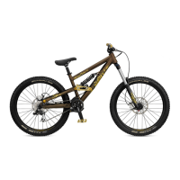
With most brake systems the distance between the brake levers and the han-
dlebar grips is adjustable. This gives in particular riders with small hands (a) the
convenience of bringing the brake levers closer to the handlebars.
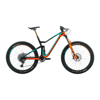
On most bikes there is a small adjusting screw near the point where the brake
cable of a cable brake enters the brake lever unit or at the lever itself. Turn this
bolt clockwise (b) and watch how the lever adjusts as you do so. Note that the
brake lever has a free travel of one third before the pressure point of the brake is
reached.
Hydraulic brakes are also fitted with adjusting devices at the brake lever. There
are different systems. Ask your SCOTT dealer for advice or read the manuals of
the component manufacturers on this SCOTT info CD.
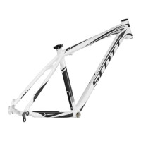
When adjusting the lever reach, make sure the first phalanx of the index finger
reaches around the brake lever (c). Check the proper adjustment and function-
ing of the brake system subsequently, as described in the chapter “Brakes” and
in the manuals of the component manufacturers on this SCOTT info CD.
DANGER!
G
Make sure your child cannot pull the brake levers all the way to the handle-
bars. Your maximum braking force must be reached short of this point.
NOTE!
I
In the case of hydraulic brakes and disc brakes follow the manual of the
brake manufacturer, which you can find on this SCOTT info CD. If you are in
doubt or if you have any questions, contact your SCOTT dealer.
b ca e fd
 Loading...