EasyManua.ls Logo

Scully ST-15C Series User Manual

Scully ST-15C Series
28 pages
To Next Page IconTo Next Page
Page #1 background imageLoading...
Page #1 background image
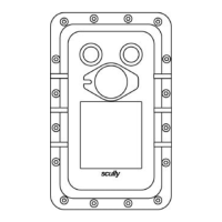
Model: ST-15C Series
Technical Manual
Single Point Overfill Prevention
Control Monitor
scully

Questions and Answers:

Scully ST-15C Series Specifications

General IconGeneral
BrandScully
ModelST-15C Series
CategoryMonitor
LanguageEnglish

Summary

General Information on Scully ST-15C Control Monitor

Description of ST-15C Control Unit

Explains the ST-15C's function as a single point overfill prevention monitor and its sensor compatibility.

ST-15C Model Designations and Suffixes

Details model suffixes (E, L, K) indicating Explosion-proof enclosure, Indicator Lights, and Key Lockable Bypass Switch.

Explosion Proof Enclosure Features

Describes the explosion-proof enclosure ('E' suffix) suitable for hazardous locations and conduit entry requirements.

Indicator Lights Functionality

Explains the meaning of the red and green indicator lights on the controller enclosure.

Bypass Control Switch Operation

Details the function of the lockable bypass switch ('K' suffix) for emergency operation.

Control Module Indicator Light

Describes the LED on the control module indicating Dynamic Self-checking (Dynacheck) operation.

ST-15C Control Output Specifications

Details the volt-free, normally open output contact rated at 250VAC, 5A for controlling valves or pumps.

User Replaceable Fuses

Lists the two user-replaceable fuses: a 1-Ampere main fuse (F1) and a 5-Ampere control fuse (F2).

Technical Specifications Overview

Provides key technical data including temperature range, power requirements, sensor types, and enclosure ratings.

Accessory Equipment for ST-15C

Mentions the necessity of plug and cable assemblies for inter-connection to vehicles.

Sculcon Junction Box and Cable Assembly

Details the SC-8B Sculcon Junction Box with 8B Green Plug & Cable for vehicle connection.

Installation Procedures for ST-15C System

Mechanical Installation Guidelines

Covers selecting a mounting location, vertical mounting, and precautions for conduit entry and sealing.

Electrical Installation Overview

Directs users to wiring diagrams and emphasizes compliance with regulations for electrical installation.

Power Connection Requirements

Details routing mains power wires through the top left-hand entry and connecting to the terminal block.

Enclosure Earth (Ground) Connection

Explains connecting a wire from the enclosure-bonding stud to the earthed metallic structure of the gantry.

Control Output Wiring

Describes routing control output wiring and connecting to output contact terminals on the terminal strip.

Intrinsically Safe Wiring Connections

Details connecting intrinsically safe signals from the ST-15C to the Sculcon Plug & Cable Unit via the bottom entry hole.

Initial System Checkout Procedure

Outlines the steps for performing initial system checkout and verification.

Recommended Test Equipment

Suggests using the Scully Model ST-2-CBE Series Tester for commissioning tests.

Operational Testing Steps

Provides instructions for applying power, checking lights, and testing permissive/non-permissive states.

System Operation During Loading

Explains how the ST-15C controller behaves during loading and in case of faults or liquid level detection.

Maintenance and Troubleshooting for ST-15C

Enclosure Inspection and Maintenance

Recommends annual inspection of the enclosure for corrosion and replacement of the inhibitor capsule.

Corrosion Protection Measures

Discusses the corrosion inhibitor capsule, its lifespan, and recommended replacement of the cover O-ring.

Control Module (Circuit Board) Maintenance

States that the internal circuitry is non-repairable and requires module replacement.

Control Module Replacement Procedure

Provides step-by-step instructions for removing and installing a replacement control module.

Indicator Lights Maintenance

Explains that LED indicator lights require no maintenance and should be replaced if faulty.

Bypass Switch Maintenance

Describes how to replace the bypass switch box or the switch itself if faulty.

Junction Box and Cable Unit Care

Offers recommendations for maintaining the Sculcon Junction Box and cable unit, especially in corrosive environments.

Troubleshooting Common Issues

Provides a guide for diagnosing and resolving common problems encountered with the ST-15C.

Appendices: Diagrams and Model Information

Control Unit Enclosure Outline Drawing

Presents dimensional drawings (DWG 31412) of the ST-15C control unit enclosure.

Sculcon Junction Box Outline Drawing

Provides dimensional drawings (DWG 63039) for the Sculcon Junction Box.

Mounting Diagram for Control Unit and Junction Box

Illustrates (DWG 61442) the typical mounting configuration of the control unit and junction box.

Installation Wiring Diagram

Shows the wiring connections (DWG 61575) required for installing the ST-15C system.

Typical Loading Rack Control Wiring Diagram

Depicts a typical loading rack control circuit (DWG 61441) showing permissive contacts.

Internal Wiring Diagram for ST-15C EL

Details the internal wiring (DWG 31392) for the ST-15C EL model.

Internal Wiring Diagram for ST-15C ELK

Details the internal wiring (DWG 31393) for the ST-15C ELK model.

ST-15C 120VAC CENELEC Models and Parts

Lists 120VAC CENELEC models and their corresponding replacement parts.

ST-15C 240VAC CENELEC Models and Parts

Lists 240VAC CENELEC models and their corresponding replacement parts.