Self-Proving Vehicle Grounding Verication System
General
Page 7.
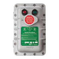
1.2.3 Optional Bypass Switch-Models ST-47-115 or 240 ELK
An optional, three position switch, is mounted on the front cover. It allows the system to operate
normally in the AUTO (center position), turned OFF (left most position), or placed in BYPASS (right
most position). In the Bypass mode, the user contact will “permit” but, both the red and green
lamps will be extinguished.
1.2.4 Optional Deadman Capability-Models ST-47-115 or 240 EL(K)/D
1.2.4.1 Permissive Contact Connection to External Devices
Terminal 4 of TB1 is factory connected to the “hot” side of the AC power line. This factory installed
jumper connecting TB1 terminals 3 and 4 can be removed if the end-user must isolate the
permissive terminals. Do not exceed the following values for the permissive terminal input and
output.
Operating and Load Voltage Range..........95 to 135 VAC
Load Current Maximum............................5 Amperes resistive
If connection is made to an external device which is neither resistive nor inductive, an interposing
relay must be used. One example of this type of external device requiring an interposing relay is a
Programmable Logic Controller (PLC). When using a relay, connect one wire of the device to TB1
terminal 5 and the other wire to AC neutral. In most instances a normally open contact of the relay
is used. One “Common” contact should make connection to whatever voltage is required by the
device to be activated. When the ST-47 is permissive, the interposing relay will energize, and
operate an external device or devices.
1.2.4.2 Deadman Switch Connection to the ST-47
Two wires (black and white) are factory connected from the Deadman switch to terminals 1 and 2
inside the Scully plug and cable box. Applicable junction boxes may be identied by the “/D” in
their Model designation. The end-user must provide wiring which connects the two terminals to
TB3 inside (bottom) of the ST-47 explosion proof housing.
OFF AUTO BYPASS
Figure 1.1 Bypass Switch Illustration (Shown in AUTO Position)
WARNING
With the OFF/ AUTO/ BYPASS Switch in the BYPASS Position,
THERE IS NO GROUND VERIFICATION PROTECTION.
 Loading...