Lock Adjustment and Operation
P:\INSTALLATION INST\Delayed Egress\INST-1511ST\INST-1511ST.vsd Rev G7 02-19 Page 12
TRIGGER
ADJUSTABLE
DISC
VERTICAL
ALIGNMENT
1511S ARMATURE
C
TRIGGER SENSOR
HORIZONTAL
ALIGNMENT
C
1511S LOCK
BODY
STEP 1. After the lock has been mounted to the door and frame per the provided template, feed the wiring
through the access hole and out to the controller board. Re-install the lock front cover onto the lock. Ensure that
the trigger sensor is aligned with the hole in the cover. The sensor is preset at the factory to slightly project through
the cover.
WARNING: DO NOT ATTEMPT TO ADJUST THE TRIGGER SENSOR LENGTH. AS THIS WILL RESULT IN
DAMAGE TO THE SENSOR AND VOID THE WARRANTY.
STEP 2. Make all wiring connections to the lock. Observe the polarity of the input power terminals. The lock
senses the power supply voltage and automatically configures itself for 12vdc or 24vdc operation. Correct power
supply voltage must be used for proper lock operation.
WARNING: INPUT TERMINALS FOR RESET, REX AND
REMOTE TRIGGER MUST ONLY BE CONNECTED TO A NORMALLY OPEN MOMENTARY DRY CONTACT SWITCH (I.E.
918 DIGITAL KEYPAD OR 728 KEY SWITCH). CONNECTION TO A VOLTAGE OR A “WET” OUTPUT MAY DAMAGE THE
LOCK AND VOID THE WARRANTY.
STEP 3. Slowly swing the door closed and visually observe the position of the armature trigger as it approaches
the trigger sensor on the lock. If the provided mounting template was used during the lock and armature installation,
the trigger & sensor should align with one another both horizontally and vertically. The LED on the back of the
trigger sensor will light when the armature trigger is detected.
IMPORTANT: CORRECT OPERATION OF THIS LOCK
DEPENDS ON THE TRIGGER SENSOR BEING ABLE TO DETECT THE ARMATURE TRIGGER WHEN THE DOOR IS
CLOSED. A PROXIMITY ADJUSTMENT CAN BE MADE TO THE TRIGGER FOR FINE TUNING. THIS IS EXPLAINED IN
STEP 4.
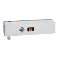
STEP 4. The small black spot located on the locks front access cover facing the door is the trigger sensor. The
TRIGGER SENSOR LED as well as the DIGITAL DISPLAY are beneficial in the testing process.
the TRIGGER SENSOR LED located on the back of the sensor can be used to check the sensors operation and
verify proper alignment and adjustment of the circular TRIGGER located on the armature assembly. The trigger
sensor LED can be viewed through the terminal block side of the lock with the cover removed. You can find this
near the speaker.
The DIGITAL DISPLAY can be used for diagnostics when the lock is in bypass mode. It uses the TRIGGER
SENSOR to sense door position so can also be used to check TRIGGER SENSOR operation.
a) “Double Dash Marks” ( ) indicate that the TRIGGER SENSOR sees the TRIGGER and that the door is closed.
b) “Six Dash Marks”( ) indicate that the TRIGGER SENSOR does not see the TRIGGER. The door is either
open or the trigger is improperly adjusted.
Set the lock to BYPASS mode by turning the built in key on the lock counterclockwise. With the lock in the bypass
mode, swing the door open. The TRIGGER SENSOR LED should be off and the digital display should show “Six
Dash Marks”. Prop your door open, place and hold a metal object (such as a coin) against the TRIGGER SENSOR
on the face of the and verify that the TRIGGER SENSOR LED turns ON and that the DIGITAL DISPLAY changes to
“Double Dash Marks”
Remove the metal object and verify that the TRIGGER SENSOR LED turns OFF and the DIGITAL DISPLAY
changes back to “Six Dash Marks”. This verifies that the trigger sensor is working.
Close the door and verify that the TRIGGER SENSOR LED turns ON. If the LED does not turn ON and the
DIGITAL DISPLAY does not change, adjust the TRIGGER on the armature assembly by turning the allen head
screw in the center of the TRIGGER counterclockwise which will extend the trigger outward toward the lock face.
Proper adjustment will allow the TRIGGER to touch the face of the TRIGGER SENSOR and be slightly depressed
with the door fully closed.
Reset the lock by turning the built in key switch momentarily clockwise. The lock should lock and the digital display
should show the delay time. Now, push the door. With slight door movement (1/8" to 1/4”) the delay process should
start with the display counting down and the alarm sounding. If the delay process does not start once the door has
moved, the circular target has been adjusted too far out and needs to be adjusted back in slightly. A properly
adjusted target will pull away from the face of the sensor with 1/8" to 1/4” of door movement and start the delay
process.
STEP 5. Activation of the 1511S can be made by door movement or an external trigger. When using the door
movement method, activation is achieved through the way the armature hardware is designed. When someone
unlatches the door and applies up to 15 lbs. pressure, the lock will hold onto the armature while simultaneously
letting the door & trigger armature move away from the lock & trigger sensor. Sensitivity in the detection of the
trigger movement can be adjusted for optimum sensitivity & performance. This adjustment can be made as
indicated in step 4. The center of the trigger or “target” is spring loaded and can be screwed in and out of the
armature thus either decreasing or increasing the space between itself and the
sensor. The “spring” feature of the target is to prevent damage from direct
contact with the trigger sensor. Depending on the accuracy of the alignment,
the trigger does not have to physically touch the sensor to operate correctly.
--
--
--
--
 Loading...