sdcsecurity.com service@sdcsecurity.com
SECURITY DOOR CONTROLS
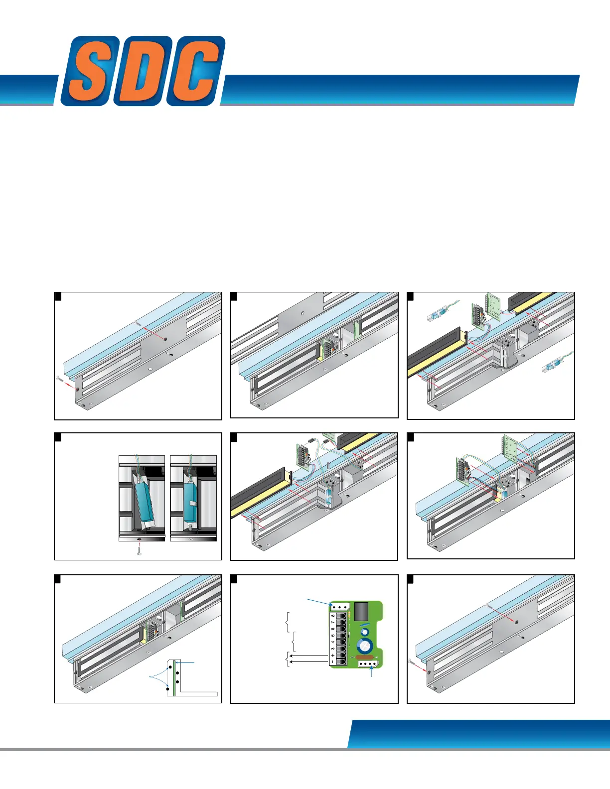
EZ Option Upgrade Kits - Emlock© 1512 / 1572
Remove cover plate screws.
1 2
Remove
cover plate.
6
Place magnetic coil firmly
between core lamination
as shown.
Connect
magnetic
bond sensor
wires to the input
module B Option
connector as shown.
5
The Magnetic Bond
Sensor should be
positioned as shown
below, after step 4.
EZ-B-10-2 MAGNETIC BOND SENSOR
Modular Kit
Remove cover plate screws.
2
Remove
cover plate.
3
6 7
Lift input module
and magnetic coil
from the case.
Place magnetic coil firmly
between core lamination
as shown.
Connect
magnetic
bond sensor
wires to the input
module B Option
connector as shown.
3
Place input module vertically
between post at each
side of case.
The Magnetic Bond
Sensor should be
positioned as shown
below, after step 4.
Cradle
Position Posts
PC Board
Input module wiring.8
B Option
Connector
B Option
Magnetic Bond Sensor
D Option
Door Status Sensor
Magnetic Core
12 or 24 VDC
LOCKED - NO
COM
UNLOCKED - NC
CLOSED - NO
COM
OPEN - NC
4
Remove 2 screw
from the case
bottom.
Place the
Magnetic Bond
Sensors at the
base of each
Magnetic Core.
Secure sensor
in place with
screw as
shown.
Remove cover plate screws.
1 2
Remove
cover plate.
6
9
Attach cover plate.
Place magnetic coil firmly
between core lamination
as shown.
connector as shown.
5
The Magnetic Bond
Sensor should be
positioned as shown
below, after step 4.
Remove cover plate screws.
1 2
Remove
cover plate.
6
9
Attach cover plate.
Place magnetic coil firmly
between core lamination
as shown.
Connect
magnetic
bond sensor
wires to the input
module B Option
connector as shown.
5
The Magnetic Bond
Sensor should be
positioned as shown
below, after step 4.
Input module wiring.8
B Option
Connector
B Option
Magnetic Bond Sensor
D Option
Door Status Sensor
Magnetic Core
Connector
12 or 24 VDC
LOCKED - NO
COM
UNLOCKED - NC
CLOSED - NO
COM
OPEN - NC
3
7
Lift input module
and magnetic coil
from the case.
43
Place input module vertically
between post at each
side of case.
Remove 2 screw
from the case
bottom.
Place the
Magnetic Bond
Sensors at the
base of each
Magnetic Core.
Secure sensor
in place with
screw as
shown.
Cradle
Position Posts
PC Board
B Option
Connector
B Option
Magnetic Bond Sensor
D Option
Door Status Sensor
Magnetic Core
Connector
12 or 24 VDC
LOCKED - NO
COM
UNLOCKED - NC
CLOSED - NO
COM
OPEN - NC
Lift input module
and magnetic coil
from the case.
4
Place input module vertically
between post at each
Remove 2 screw
from the case
bottom.
Place the
Magnetic Bond
Sensors at the
base of each
Magnetic Core.
Secure sensor
in place with
screw as
shown.
Cradle
Position Posts
PC Board
Remove cover plate screws.
1
9
Attach cover plate.
5
The Magnetic Bond
Sensor should be
positioned as shown
below, after step 4.
While a Door Status Sensor indicates the door is open
or closed, SDC’s Magnetic Bond Sensor provides higher
security monitoring by indicating the locked / unlocked
mode, tampering and low voltage. The use of
both the door status and magnetic bond sensor is
recommended for high security applications.
Application: Lock secure status annunciation,
mantrap system logic,
CCTV camera activation.
Output: 2 Contacts provided
2-SPDT Dry Contact,
250 mA @ 12/24VDC
Specify 2 for 1512, 1572