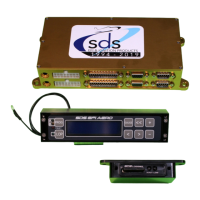
11
Lycoming Crankshaft Hall sensor mounting
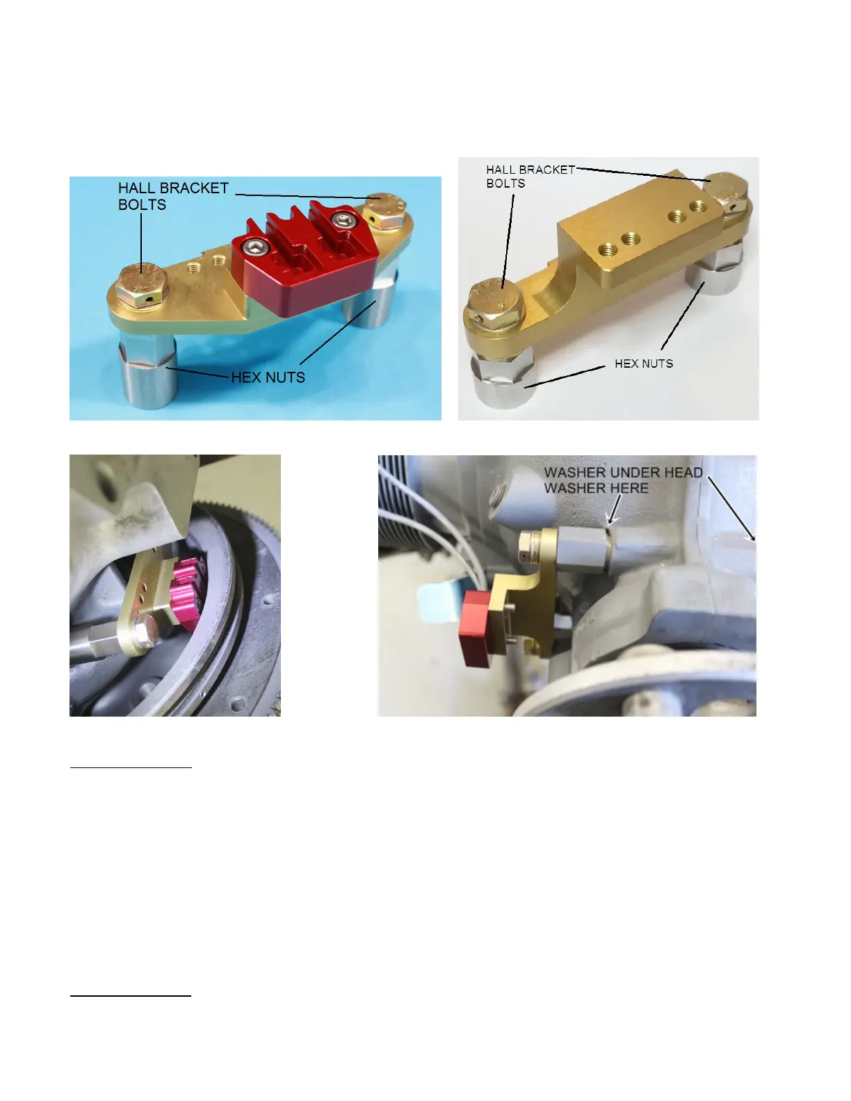
We provide CNC’d Hall sensor mounts for 4 and 6 cylinder Lycomings using the 9.75”O.D. flywheel.
The hall sensors are offered in a single or dual setup for single or dual ECUs. The mounts can accept
either type. The mounts have multiple 10-32 threaded holes to attach cable protection shields if users are
concerned about a thrown or broken belt damaging the Hall sensor cables.
Wide mount for 3.50” spacing & dual Hall sensor. Narrow mount for 3.25” bolt spacing.
Wide 3.5 mounted rear view. Narrow 3.25 mounted front view.
Case Bolts install: On 540 engines, the upper fastener is a stud instead of a bolt as on the 4 cylinder
engines.
CNC’d mounts bolt to the front most Case Bolts on the right side of the case.
Steps to install the Case AN-6 bolts are as follows:
Setp 1. Remove your front most case bolts, original nuts will not be used as new longer hex nuts are
provided.
Step 2. Place one standard washer under the head of each Case Bolt. Factory washer is okay to use.
Step 3. From the case left side, pass the Case Bolts through the case so threads protrude on the case
right side.
Step 4. Place a washer onto each case bolt.
Step 5. Thread case bolts into the Hex Nuts provided
Step 6. Snug case bolts for now, final torque should be done after clearance checking.
Hall Bracket Bolts: Place one washer onto each Hall Bracket Bolt. Pass Hall Bracket bolts through the
gold Hall mount bracket, into the hex nuts provided. One issue only with the 3.25” bracket which can
occur is the Hall Bracket Bolt collides with the Case Bolt inside the Hex Nut. If this occurs remove Hall
 Loading...