28
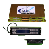
EM-6 16 position Molex connector
Ground wires. Important!
All ECU’s. See image right, connect two black ground wires at left edge of
connector to a grounding buss with no other wires shared at the same
connection point.
Dual ECU there will be 4 ground wires total from the two connectors.
These should always be grounded even if the system is being used for ignition
only(no injectors) which is done on rare occasions.
Octane Switch and Closed Loop Enable
These are optional wires, yellow for Octane switch pin10, and
white for Closed Loop Enable pin9. These wires can be
inserted if these two options are required. Connect to switch
with other switch terminal to ground. Option is active when the
input is grounded by the switch. If you intend to run Closed
Loop the switch on pin 9 is highly recommended.
Fault LED
Only supplied if the system comes with the 3-1/8 round
programmer. The Design1 rectangular programmer has the Fault
LED built in. On your panel you must insert the wiring through the
front hole in your panel, then route wires to the ECU and 12V
source. Panel mount Fault LED black wire gets inserted into pin 11
of the 16 pin molex plug. Red to +12V, 2A breaker. Panel hole size
¼” diameter.
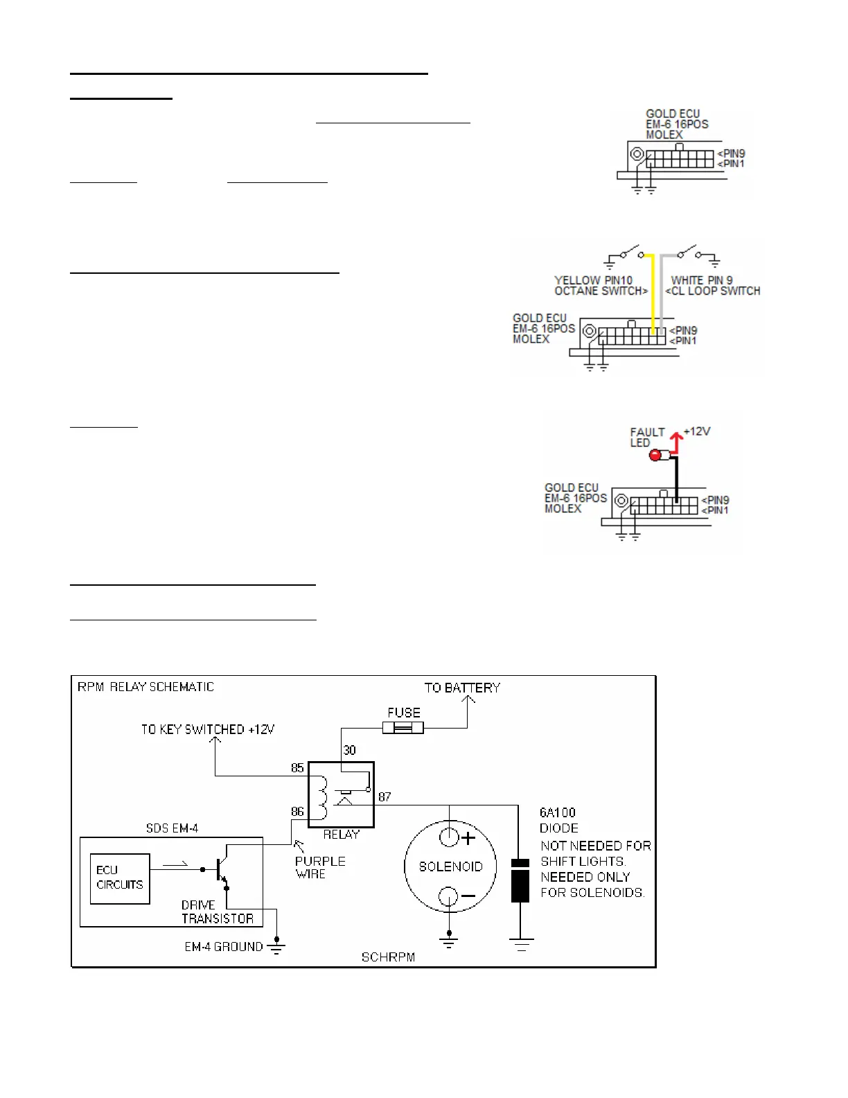
Brown 20 gauge, pin 2 white Molex: This supplies fuel flow data output (optionally enabled)
Purple20 gauge, pin 3 white Molex: Optional rpm switch, commonly used on VVT (Honda VTEC)
systems.
Ground switched. Hookup schematic below:
 Loading...