+44 (0)1543 443060
sales@secontrols.com
www.secontrols.com
Please keep these operating instructions for future reference and maintenance.
Subject to technical modications. Diagram is not binding.
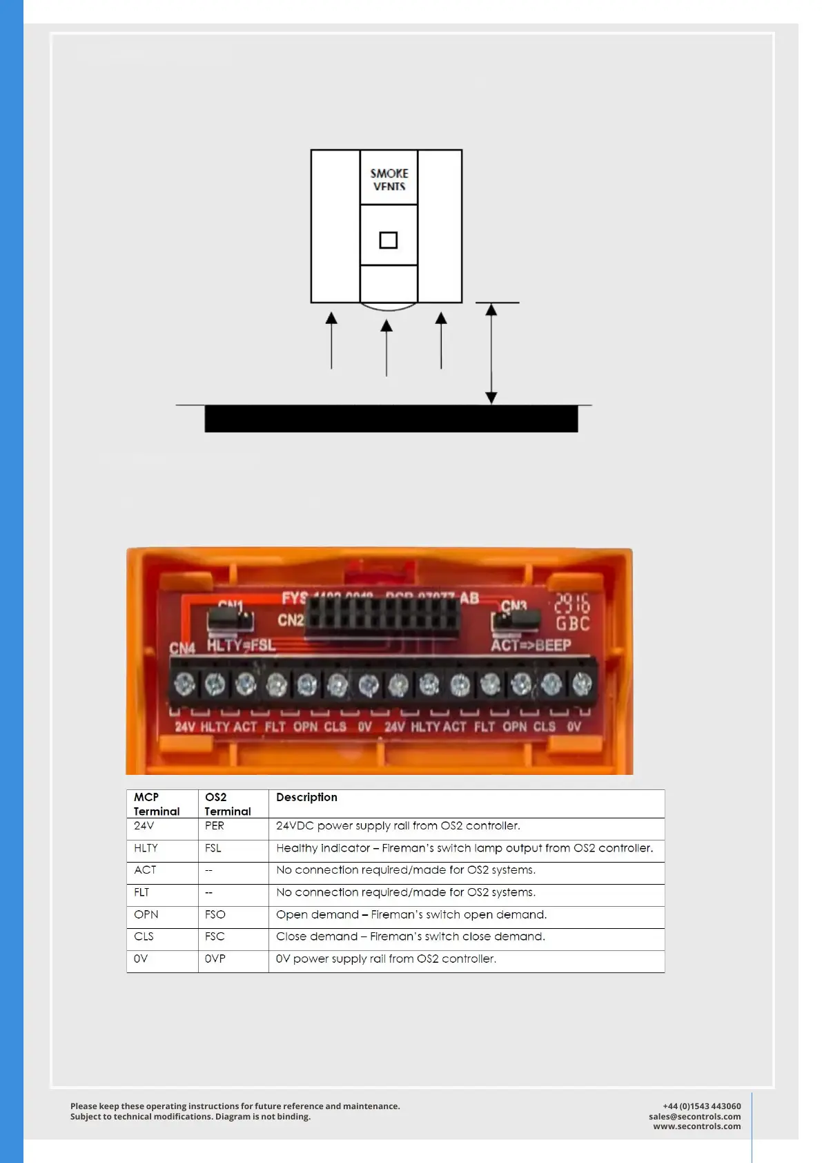
Installation Position.
It is important that the MCP is located a minimum 150mm away from any obstruction below.
This is to enable the xing screws to be tightened correctly and to allow access to the reset
key slot in the underside of the unit.
Installation Position.
All connections to the OS2 MCP are made via the connection PCB mounted within the
adapter plate assembly. (See diagram below).
The jumper CN1 must be tted in the left hand (“HLTY=FSL”) position.
The jumper CN3 enables and disables the sounder. The default is enabled (left)
The MCP must be secured using the two xing screws (Torx-T8) on the underside of the MCP
 Loading...