EasyManua.ls Logo

Se-Kure Controls SK-800KME Series User Manual

Se-Kure Controls SK-800KME Series
4 pages
To Next Page IconTo Next Page
Page #1 background imageLoading...
Page #1 background image
Installation Instructions for the
ME Jr. plus 2 Alarm System
SK-800KME Series
SK-3690
(Optional) “Where it’s At Light”
SK-807ME
ME Jr. plus 2 (8) Port Splitter Box
SK-80108ME
ME Jr. plus 2 (8) Port Strip
SK-809
Telephone Modular
“End Plug”
SK-800KME
ME Jr. plus 2 Alarm Module
Battery Installation:
1. Remove the screw that restricts the battery
door from opening using a phillips head
screwdriver as shown in Fig. 1.
2. Insert the key and turn it to the disarmed
position (the key cannot be removed in the
disarmed position).
Note: The battery door will not open without the
key in the lock and in the disarmed position.
3
. Remove the battery door.
4
. Before installing batteries, plug the (SK-195)
AC/DC Power Supply into the Alarm Module
jack marked Pwr. Input as shown in Fig. 2.
5
. Install (4) fresh “C” Cell Alkaline batteries
following (+) and (-) polarity shown in Fig. 3.
VERY IMPORTANT! When installing batteries,
always follow the polarity indicated on the
battery holder.
6
. Close the door as shown in Fig. 4. The horn
will “Double Chirp” until the door is securely
closed.
7
. Replace the battery door retaining screw as
shown in Fig. 5. (If the key is in the disarmed
position for 1-1/2 minutes, the horn will
Single Chirp” every 15 seconds to indicate
that the unit is in the disarmed mode.
Fig. 1
Fig. 2
Fig. 3
Fig. 4
Fig. 5
SK-847-x
Extension
Connects
Alarm Module
to Splitters &
Strips &
Splitters to
Splitters
ME Jr. Terminals
Question and Answer IconNeed help?

Do you have a question about the Se-Kure Controls SK-800KME Series and is the answer not in the manual?

Se-Kure Controls SK-800KME Series Specifications

General IconGeneral
BrandSe-Kure Controls
ModelSK-800KME Series
CategorySecurity System
LanguageEnglish

Summary

Battery Installation

Accessing Battery Compartment

Remove screw, unlock with key, and remove the battery door.

Power and Battery Setup

Connect power supply and install four "C" Cell Alkaline batteries, noting polarity.

Securing the Unit

Close the door, secure with screw, and note disarmed mode indicators.

System Status Indicators

Circuit and Keypad Lights

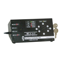
Explains status lights for circuits, keypad program, and key/keypad disarm.

Power and Battery Indicator Lights

Describes AC Power and Low Battery indicator lights.

System Installation and Connectivity

Circuit Configuration

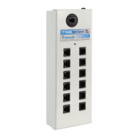
Details the two circuits, daisy-chaining splitters/strips, and end plug requirements.

Connecting Components

Instructions for connecting splitters/strips using cables and installing sensors.

Sensor Selection Guide

Lists available sensor types for display products, including straight and coiled options.

Keypad Operation and Programming

Keypad System Features

Dual control with mechanical key and keypad; Auto-Arm feature.

Keypad Access Code Change

Step-by-step guide to changing the default 4-digit security code.

Infrared Remote Setup

Dip Switch Configuration

Arrange dip switches on the alarm module and remote for encoded signal.

Recommended Settings Change

Advised to change factory default dip switch settings for security.

Related product manuals