EasyManua.ls Logo

Se-Kure Controls Mini T Series - User Manual

Se-Kure Controls Mini T Series
2 pages
Print Icon
To Next Page IconTo Next Page
Loading...
Se-Kure
Controls,
®
Inc.
3714 Runge Street  •  Franklin Pk., IL 60131-1112  •  1-800-322-2435  •  (847) 288-1111 Fax: (847) 288-9999
www.se-kure.com  •  email: info@se-kure.com
1. Remove the screw
at the top of the alarm
module with a Phillips
Head Screw Driver.
Insert the key and
turn it clockwise to
open the box.
3. Close the Lid and
turn the key “counter
clockwise” to lock the
box. Then, replace
the screw at the top
of the alarm module.
Note: The AC/DC Power Supply is the primary power source for the alarm.
When connected, it powers the alarm and the LED lights. If the AC power is
cut off, the sensor lights will go out, but the alarm still functions, using the
battery back-up power.
2. Install (6) new “AA”
Alkaline batteries
(Not Included) onto
the battery holder as
shown in the image at
right.
The Mini T-Series Alarms use the entire line of
Se-Kure Sensors. Ask your Customer Service
Representative for additional information.
4. Plug the AC/DC
Power Supply into a
standard 110-115v
AC outlet and the
other end into the
Power Supply Jack
on the Alarm module.
Battery Installation:
Mini T-6 & T-12 Alarm Instructions
(6) “AA” Alkaline Batteries
Unit
Requires
6
Batteries
(Not
Included)
SK-110
Extra Single Bit Key
SK-195
AC/DC Power Supply
SK-T6MA-W
SK-T12MA-W
Follow the (+) & (-)
Polarity Markings on
the battery holder.
Question and Answer IconNeed help?

Do you have a question about the Se-Kure Controls Mini T Series and is the answer not in the manual?

Summary

Battery Installation Guide

Open the Alarm Module

Remove the top screw, insert the key, and turn clockwise to open the alarm module box.

Install Backup Batteries

Install six new 'AA' alkaline batteries, ensuring correct polarity is observed.

Secure the Alarm Module

Close the lid, turn the key counter-clockwise to lock, and replace the top screw.

Connect AC;DC Power Supply

Plug the AC/DC power supply into a standard outlet and the alarm module's power jack.

Primary vs. Backup Power

The AC/DC supply is primary; batteries provide backup power when AC is interrupted.

Alarm Module Testing & Operation

Initial Sensor Check and Key Position

Install an 'LE' sensor, ensure it is closed, and turn the key to the 'ON' position.

System Status Indicators

Understand LED lights for sensor location, AC power, and low battery warnings.

Sensor Attachment Preparation

Crucially, clean product and sensor surfaces with alcohol prep pads before attachment.

Connecting Sensors and Module

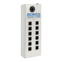
Plug sensors into the alarm module ports to secure items, supporting up to 6 or 12.

Operating and Tampering Modes

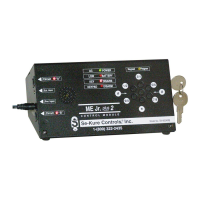
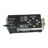
Unit scans ports when 'ON'; 'Stand-By' mode allows sensor changes and warns of tampering.

Alarm Reset Procedure

After an alarm, turn the key to 'Stand-By' to reset, then back to 'ON' after correcting the issue.

Overview

The document describes the Mini T-6 & T-12 Alarm System, a security device designed to protect merchandise using sensors.

Function Description

The Mini T-Series Alarm System is a security module that monitors connected sensors for tampering. It utilizes a key-operated switch to control its operational modes: "ON" and "Stand-By." When in the "ON" position, the alarm module actively scans its sensor ports for any signs of tampering, such as sensor removal from the alarm module or merchandise, insertion of metal objects into open sensor ports, or attempts to short out a sensor. The system also continuously checks its AC power and battery condition, indicated by a GREEN light. If AC power is cut off, the alarm functions using battery backup. In "Stand-By" mode, the unit temporarily deactivates its alarm function, allowing for the addition or removal of sensors. During this mode, it emits a "BEEP" every 30 seconds to remind employees to reactivate the system. The system uses a horn for audible alarms and RED indicator lights to identify which sensor triggered an alarm.

Important Technical Specifications

  • Models: Mini T-6 (6 sensor ports) and Mini T-12 (12 sensor ports).
  • Power Source:
    • Primary: SK-195 AC/DC Power Supply (standard 110-115v AC outlet).
    • Backup: 6 "AA" Alkaline Batteries (not included).
  • Key: SK-110 Extra Single Bit Key.
  • Sensors: Compatible with the entire line of Se-Kure Sensors (specifically mentions "LE" sensors).
  • Indicators:
    • GREEN light: Indicates operating status (AC/battery powered condition) and good battery condition in battery mode. Flashes with a "BEEP" for low battery.
    • RED light(s): Flashes for 5 seconds upon unit turn-on to indicate sensor detection and correct operation. Continues to flash after an alarm to identify the triggered sensor.
  • Alarm Output: Audible horn for alarms.

Usage Features

  • Key Operation: The system is controlled by a key.
    • "ON" Position (LEFT): Activates the alarm system, allowing the unit to scan for tampering. The key can only be removed in this position.
    • "Stand-By" Position (RIGHT): Temporarily deactivates the alarm to allow for sensor addition or removal. The key cannot be removed in this position. The unit beeps every 30 seconds in this mode.
  • Sensor Connection: Sensors plug into the designated ports on the alarm module.
  • Sensor Attachment: Sensors are attached to merchandise using adhesive pads. A critical cleaning step is required: clean the product area and sensor bottom with alcohol prep pads, then dry thoroughly with a paper towel until clean.
  • Alarm Reset: After an alarm, insert the key and turn it to the "Stand-By" position. Correct the problem/sensor, then turn the key back to the "ON" position.
  • Power Supply: The AC/DC power supply is the primary power source. When connected, it powers the alarm and LED lights. If AC power is lost, the sensor lights will go out, but the alarm will continue to function using battery backup.

Maintenance Features

  • Battery Installation:
    1. Remove the screw at the top of the alarm module.
    2. Insert the key and turn it clockwise to open the box.
    3. Install 6 new "AA" Alkaline batteries into the battery holder, following polarity markings.
    4. Close the lid and turn the key counter-clockwise to lock the box.
    5. Replace the screw at the top of the alarm module.
  • Low Battery Indication: The GREEN indicator light will continually flash along with a "BEEP" from the horn, signaling low battery.
  • Sensor Cleaning: Prior to attaching sensors, the product area and sensor bottom must be cleaned with alcohol prep pads and thoroughly dried. This step is crucial for forming a good bond.

Se-Kure Controls Mini T Series Specifications

General IconGeneral
BrandSe-Kure Controls
ModelMini T Series
CategorySecurity System
LanguageEnglish

Related product manuals