Do you have a question about the Se-Kure Controls Klothing Kontrols SK-3600 Series and is the answer not in the manual?
| Type | Security System |
|---|---|
| Color | Black |
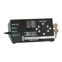
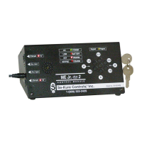
| Model | SK-3600 Series |
| Manufacturer | Se-Kure Controls |
| Alarm Type | Audible Alarm |
Explains the meaning of Green, Red, and Yellow LED flashes for unit operation, alarms, and programming.
Instructions for installing six "AA" Alkaline Batteries, emphasizing correct polarity.
Steps for attaching the Alarm Module to a display using the U-Bolt and nuts.
Describes testing by plugging in sensors and arming the unit to check port activation.
The Green LED flashing every 15 seconds indicates good battery condition.
Red LEDs flashing for 5 seconds indicate the specific sensor that caused an alarm.
The GREEN indicator light flashing and beeping signals a low battery condition.
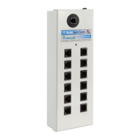
Highlights features like key lock replacement, program mode, and auto-arm functionality.
Explains initial use of the keypad and the factory default access code.
Step-by-step guide to changing the security access code on the keypad.
Procedures for disarming the alarm module and connecting sensors to merchandise.
How to activate the alarm, what constitutes tampering, and how the unit scans ports.
Instructions for installing and using the optional "Flashing Light" accessory.
Guidance on adding/removing sensors and resetting the alarm module after an event.