16
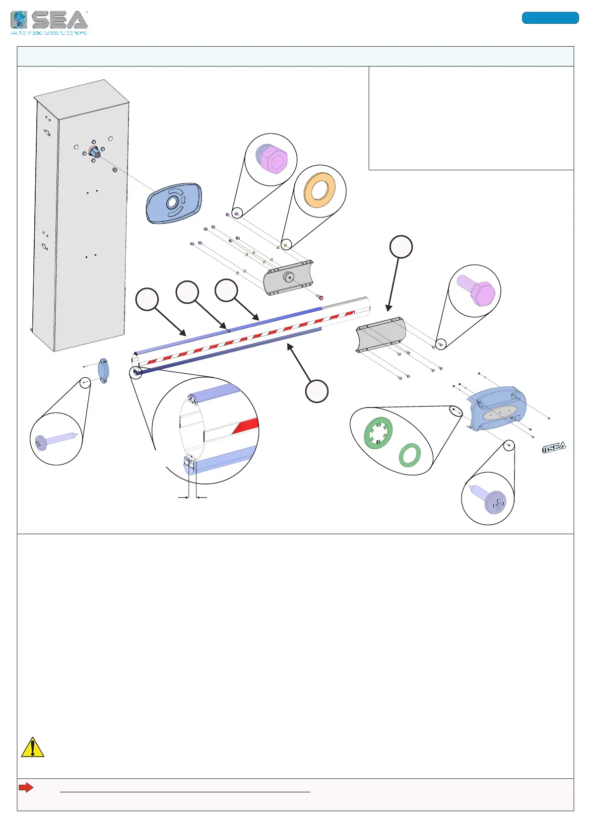
5 - ARM INSTALLATION ON THE BARRIER
A
B
C
D
E
A - ARM FIXING BRACKET
5 mm
B - ANTI-BLUNT RUBBER PROFILE
C - PLASTIC PROFILE FOR LED INSERTION
D - JOINT FOR PLASTIC PROFILE MODULES
E - PLASTIC PROFILE FOR LED INSERTION
For arms longer than 4 meters, it is recommended to install the fork support on the ground (to be
installed at the end of the arm) or to install the folding support (to be installed on the arm)
The «LIGHT TH» arm for SPRINT barrier is supplied in a single module for lengths up to 3 meters, and in two
modules «FIX» + «MB» with joint, for lengths over 3 meters.
For the assembly of the modules, please refer to the arm technical instructions.
5.1. I L (L )
The plastic profile must be mounted on the upper side of the arm;
Insert the first module of the plastic profile «C» in the guide up to the edge of the arm fixing bracket «A»;
Insert the joint «D» followed by the next plastic profile module «E» - repeat for the following modules, each
spaced out by the joint, until the end of the arm; cut out the exceeding module, if necessary.
5.2. I -
The anti-blunt rubber profile must be mounted on the lower side of the arm;
Insert the rubber profile «B» in the guide, sliding up to the edge of the arm fixing bracket «A»;
CUT OUT THE EXCEEDING RUBBER PROFILE MAKING SURE IT COMES OUT OF THE ARM FOR 5 mm - Fig. 13a
Fig. 13
Fig. 13a
International registered trademark n. 804888
ENGLISH