19
Fig. 19a
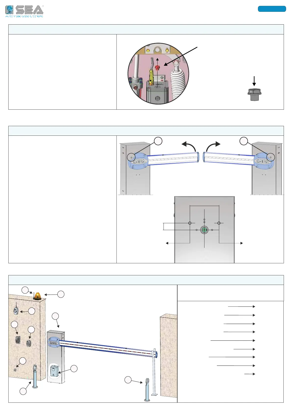
11.1. The Fig. 19 shows the drilling holes
diagram for the passage of the power
cables of the barrier lights;
11.2. If the arm is left-hand installed - Fig.
19a, then use hole «A» - Fig. 19
11.3. If the arm is right-hand installed -
Fig. 19b, then use hole «B» - Fig. 19
A
A
142
49
Ø 10 mm
B
B
Ø 10 mm
Fig. 19b
Fig. 19
11 - DRILLING HOLES DIAGRAM FOR LED LIGHTS CABLES PASSAGE
1) B
ARRIER (MOTOR)
2) PHOTOCELL TX
3) PHOTOCELL RX
4) FLASHING LAMP
5) A
NTENNA
6) EXTERNAL RECEIVER
7) KEYPAD
8) K
EY-BUTTON
9) D
IFFERENTIAL 16A/30mA
10) CONTROL UNIT BOX
RECOMMENDED CABLES NUMBER AND SECTION
FOR WIRINGS ON CONTROL UNIT
* Increase the cable section in case of high
distance from the control unit
Example of barrier and accessories
installation
4 X 1,5
2 X 0,5
4 X 0,5
2 X 0,5
4 X 0,5
4 X 0,5
4 X 0,5
3 X 1,5 *
1
2
3
4
5
6
7
8
9
10
Fig. 20
1 X RG58
12 - ELECTRIC WIRINGS
10 - BREATHER CAP REPLACEMENT
10.1. Before starting the barrier, remove
the red transport cap and replace it with
the black one supplied and equipped with
the airhole;
The cap is on the top of the hydraulic unit
- Fig. 18
On SPRINT BR model the cap is hidden
behind the switching, so pass the hand
behind the metal support to unscrew the
cap.
Fig. 18
REPLACE IT
WITH THE BLACK
BREATHER CAP
REMOVE THE RED
TRANSPORT CAP
International registered trademark n. 804888
ENGLISH