PUMP MOUNTING INSTRUCTIONS
3
page
2
page
Failure to do this prevents the pump from starting when water is present.
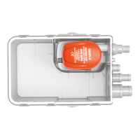
Step 1: Press the hasps on both sides of the auto bilge pump, and remove the filter away from the bottom of
the pump.
NOTE: Before connecting or operating the pump, install the filter correctly. It is strictly prohibited to disconnect
the filter when the pump is running.
The pump must be installed above the water level.
WARNING: Remove the pump mounting base (See Figure 3)
Remove the foam block that supports the float during shipping.
Step 2: Ensure the best place when installing the pump. If you only use one pump, it is usually installed in the
deepest place of the water level when the boat stops. You must install complete tubes for draining water.
Drain all sweeper by horizontal installation of water pipes, or placing the pump in a higher position.
Step 3: Install the strainer
A: When fixing the strainer on wood block, use ¢ 4.0mm stainless steel self-tapping screws.
B: If you fix the strainer to a metal or glass fiber, firstly install a piece of wood on it, then fix the strainer to the
piece of wood, then install the pump in the filter, and ensure that the two hasps fastened.
Step 4: Connect a 3/4 "/1-1/8" ID pipe to the outlet nozzle, and clamp them by a stainless steel clamp.
Recommend using the standard tubes, because they will not tie off by suddenly bending. If using a pipe with
smaller diameter, it will not damage the pump, but will reduce the pump's flow.
Step 5: Wire
In order to prevent ruin or corrosion of the wire, it is important to fasten the ends of the wire and the terminals
by insulators or plastic belts at the highest horizontal position as possible.
When installing the pump, # 18 wire is suggested, If too small wire is used, it will cause overheating inside,
reducing the pressure and affecting the performances of the pump.
NOTE
4. Mark location of the three (3) mounting holes with a pencil or scribe.
6. Slide hose clamps (one to clamp hose to the pump, the other to the
thru-hull connector) over end of the hose. Force hose over the
discharge nozzle of the pump. Install clamp.
WARNING: When drilling holes do not drill through the hull!
1. Make sure the hull thickness is at least 1/2" thick. If not, place a block of 1/2" marine plywood (slightly
larger than the pump base) in the lowest part of the bilge. Be sure that the pump cover can be removed for
cleaning in this position. Glue the plywood to the hull with a waterproof adhesive (epoxy, silicone adhesive,
or fiberglass resin). See figure 1.
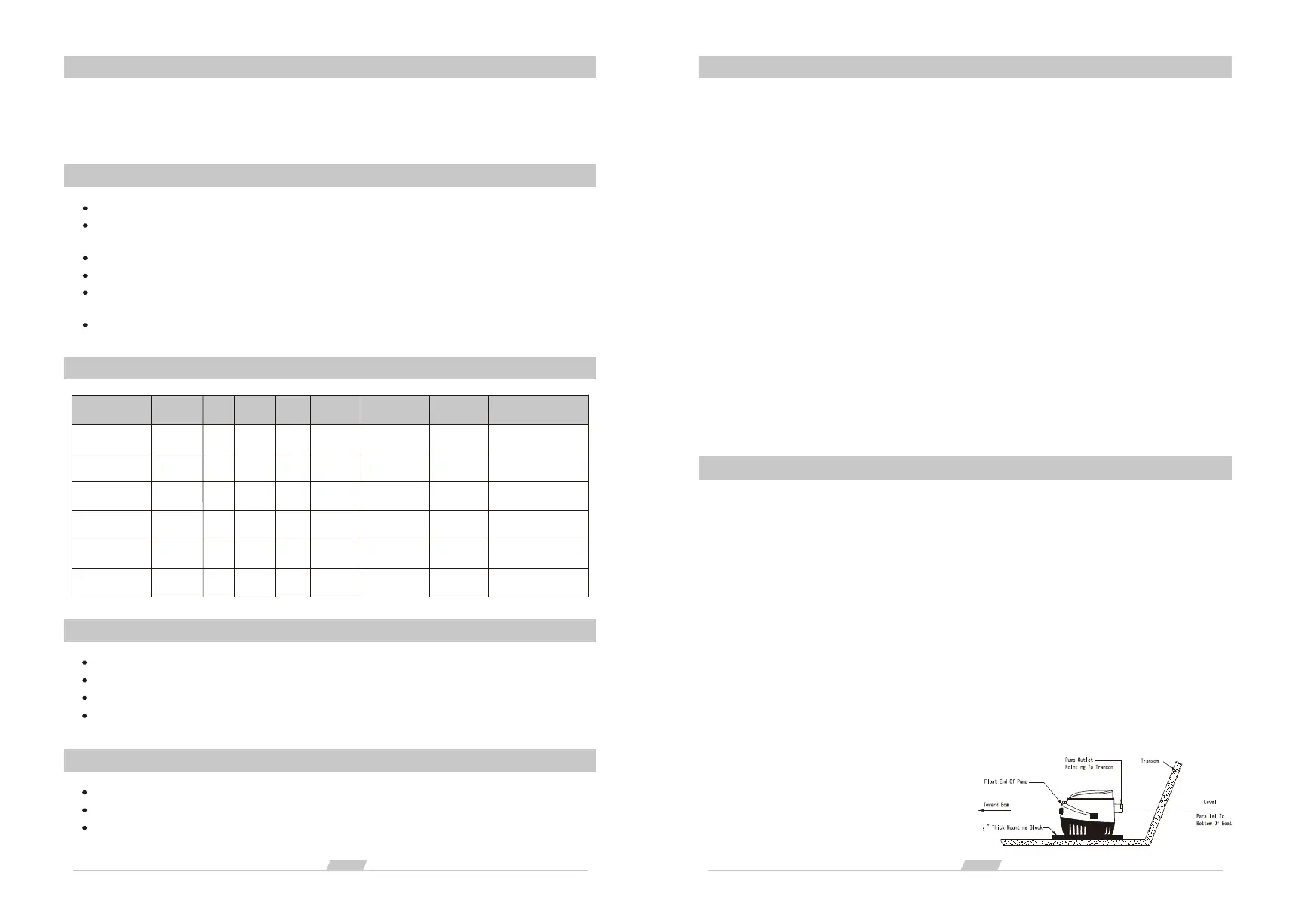
Be sure outlet nozzle is level. If pointed upward or downward, an airlock may form in the pump.
(See Figure 1)
3. The float end of the pump must be level with or above the pump end (See Figure 1). This prevents the
pump from running out of water while the float is still high enough to activate the pump.
2. Position the pump in the lowest part of the bilge on a flat, level surface (on the plywood block if it has been
installed) with the outlet pointing toward the transom.
5. Carefully drill two 1/8" diameter pilot holes in marked area and drive a screw in each hole.
7. Route hose on an upward incline to the thru-hull connector.
Avoid dips in hose that can trap water and airlock
the pump. Avoid putting excess tension on
hose, which can damage the pump outlet.
8. Force the hose over the thru-hull boards and
clamp into place.
Figure 1
CAUTION
Read all instructions carefully before installing and using this product.
This pump is sealed and, therefore, submersible. However, the electric wire connections must not be
submerged. For extra protection, coat the butt joints and adjacent wire ends liberally with liquid electrical tape.
SECURITY
Not dry running.
All wires and connections must be above the bilge water level. Unless necessary, please do not
arbitrarily remove the insulator. Marine sealant oxidant should be used for all wires.
The wire connections must be sealed by marine sealant.
While installing, connect the pump's black wire to the negative (-) terminal and brown or brown white wire
to the positive pole (+).
Use the suitable fuse.
Auto bilge pump can only be used for pumping water. It can not be used for other liquids.
SPECIFICATIONS
Model
SFBP1-G600-06
SFBP2-G600-06
SFBP1-G750-06
SFBP2-G750-06
SFBP1-G1100-06
SFBP2-G1100-06
Flow Rate
600GPH
600GPH
750GPH
750GPH
1100GPH
1100GPH
Volt
12V
24V
12V
24V
12V
24V
Current
2.5A
1.5A
3.0A
1.6A
3.0A
1.8A
Head
2.5M
2.5M
3.0M
3.0M
4.0M
4.0M
Wire Lead
1M
1M
1M
1M
1M
1M
Outlet Dia
19mm / 3/4"
19mm / 3/4"
19mm / 3/4"
19mm / 3/4"
29mm / 1-1/8"
29mm / 1-1/8"
N.W./G.W.
0.47 / 0.5kg
0.47 / 0.5kg
0.47 / 0.5kg
0.47 / 0.5kg
0.47 / 0.5kg
0.47 / 0.5kg
Dimensions(L × W × H)
147 × 83 × 103 mm
147 × 83 × 103 mm
147 × 83 × 103 mm
147 × 83 × 103 mm
147 × 83 × 103 mm
147 × 83 × 103 mm
WARNING
Always use the fuse amperage rating specified for your pump model.
To prevent injury, always disconnect the power source when installing or servicing any electrical product.
DO NOT use pump to remove gasoline oil or other flammable liquids.
Failure to do so could result in serious personal injury or fire hazards.
OPTIONAL MATERIALS
1/2"-thick marine plywood block (slightly larger than pump base).
Waterproof adhesive (epoxy, silicone adhesive, or fiberglass resin) to mount block.
18-gauge wire (brown brown white and black).
 Loading...