Do you have a question about the Seaflo 56A Series and is the answer not in the manual?
Instructions on how to adjust the pump's shut-off pressure using a 2mm Allen wrench.
Guide on adjusting the bypass valve pressure using a 2mm Allen wrench.
Highlights core features such as variable speed, 5-chamber design, safety bypass, and self-priming.
Details typical uses for the pump, including RVs, yachts, and pressurized water systems.
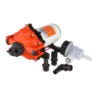
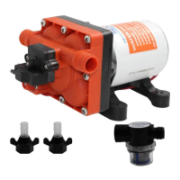
Lists all necessary materials and components required for the pump installation process.
Provides instructions on pump mounting, plumbing, and general setup for optimal operation.
Provides guidance on wire sizing based on distance for electrical connections.
Covers diagnosis for pulsating flow, failure to prime, motor issues, and low flow.
Outlines the process for adjusting the pump's shut-off and bypass pressure settings.
Lists available repair kit components for servicing the pump.
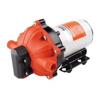
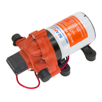
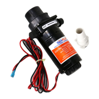
The SEAFLO 56A and 56C Series Variable Speed Smart Pump is a 5-chamber diaphragm pump designed to provide constant water pressure across multiple outlets. It eliminates the need for traditional pressurized tanks and pressure switches by utilizing integrated electronic controls and variable speed technology. This design aims to reduce cycling and noise, offering a more stable and precise control of water pressure.
The pump operates using a spring-loaded bypass valve to maintain smooth performance as water demands fluctuate. When a faucet is opened, the pump provides full water flow, and the bypass valve closes. When there is little to no water demand, the bypass valve opens, allowing water to flow back from the outlet to the inlet side, which helps maintain a steady flow and prevents excessive cycling. The variable speed technology allows the pump to adjust its output based on demand, ensuring consistent pressure. It is designed to supply up to four fixtures simultaneously.
The pump incorporates a demand switch that enables more precise pressure control and stable performance. This switch also contributes to a low starting pressure, which helps protect the pump from frequent starts. The switch is designed for good heat dissipation, being in direct contact with the liquid, which serves as a cooling function to prevent burnout. Its sealing performance is also enhanced.
The device is self-priming and can run dry safely, making it suitable for various applications such as yacht/RV/caravan pressurized water systems, sprayer fixtures (vehicle-mounted sprayers, electric sprayers), solar water systems, and other pressurization systems. It includes safety features like low voltage protection and is ignition protected.
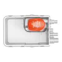
The pump can be mounted in any position, though vertical mounting with the pump head in the down position is recommended to prevent leakage into the motor casing in case of a malfunction. The mounting feet should be secured without over-tightening to allow for proper noise and vibration dissipation.
For optimal performance, the intake hose should be a minimum of 1/2" (13 mm) ID reinforced hose, with a collapsing strength of twice the inlet collapsing pressure. The main distribution line from the pump outlet should also be 1/2" (13 mm) ID, and branch and individual supply lines to outlets should be no smaller than 3/8" (10 mm). The system should be plumbed using high-pressure (2x pump rating), braided, flexible tubing to minimize vibration and noise. Inlet pressure should not exceed 30 psi, and it's generally best to avoid any inlet pressure completely. Kinks or fittings that could cause excessive restrictions should be avoided. A strainer should be attached to the inlet side, and all fittings must be secured to prevent leakage. Hose clamps should be used at both ends of the hose to prevent air leaks. If a check valve is installed, it must have a cracking pressure of no more than 2 psi.
When applying a sealer or plumbing tape, care must be taken not to overtighten, as this could lead to material being sucked into the pump. The pump should be wired on its own dedicated circuit, with the positive lead (red) connected to the positive terminal of the battery and the negative wire (black) to the negative terminal. An easily accessible switch should be installed to control electricity to the pump, allowing it to be turned off when not in use for extended periods or when the tank is empty. The electrical circuit requires protection with an over-current device (fuse) in the positive lead. The pump requires a 15A @ 12V or 8.5A @ 24V fuse, and the pump circuit should not include any other electrical loads. Proper wire sizing for the length of wire used is important, as referenced in the electrical information chart. After installation, the voltage at the pump motor should be checked while the pump is operating to ensure full voltage is available.
Bypass adjustment should ideally be performed by a professional technician using a proper gauge and equipment. Improper adjustment can cause the pump to work improperly. The pressure setting for full bypass must be at least 8psi higher than the pump's shut-off pressure to prevent the bypass and switch shut-off from overlapping, which would prevent the pump from shutting off. While the bypass comes preset for optimal operation, users can adjust it if their application requires a different setting by carefully tightening the screw to increase or loosening it to decrease the minimum operational pressure.
The pump's shut-off pressure can be adjusted using a 2mm Allen wrench. Turning the screw clockwise raises the shut-off pressure, and turning it counter-clockwise lowers it. Similarly, the bypass pressure can be adjusted using a 2mm Allen wrench; clockwise turns raise the bypass start and full bypass pressure, while counter-clockwise turns lower them.
Flexible potable water hose or PEX tubing is recommended over rigid piping. If rigid piping is used, a short length of hose between the pipe and the pump should be provided to avoid noise and vibration. The use of metal fittings is not recommended; plastic fittings should be used when possible.
Regular sanitizing and maintenance are crucial for the pump's performance. The pump should be maintained and winterized at appropriate times, especially before and after periods of storage. Any actions outside the recommendations in the instruction manual may damage the pump, and such damage is not covered by warranty.
| Model | 56A Series |
|---|---|
| Voltage | 12V DC or 24V DC |
| Amps | 5.5A @ 12V DC / 3.0A @ 24V DC |
| Self-Priming | Yes |
| Current | 5.5A @ 12V DC / 3.0A @ 24V DC |
| Operating Temperature | 140°F (60°C) Max |