EasyManua.ls Logo

Seaflo 06 Series - User Manual

Seaflo 06 Series
2 pages
Print Icon
To Next Page IconTo Next Page
Loading...
Automatic Bilge Pump Manual
06 Series
1
page
4
page
WARNING INSTRUCTIONS
WARNING: Be certain that power source is 12-volt D.C. / 24-volt D.C. Higher voltage will damage the pump.
4. Install a Three-way switch that allows for automatic or manual
switching models.
1. Using the full length of wire provided (and additional wire if necessary), connect wires to the pump as shown
in the diagram.(See Figure 2.)
3. Using butt connectors sized for 18-gauge wire, splice fuse holder into positive lead (brown) between the
battery and switch.
Position fuse holder in a location that is easily accessible for changing fuses.
IMPORTANT: Use fuses of the proper amperage (See Specification Chart at top of sheet.)
WARNING: Failure to properly fuse and make the appropriate waterproof
connections will void the product warranty.
5. Turn the pump on and twist the Test Knob clockwise to check
operation. Feed water into the pump. If output appears to be
too low, check the wire connections. Reversed connections
result in opposite impeller rotation that drastically reduces
capacity and can cause premature pump failure.
2. Route wires out of the way and secure them to the bulkhead to avoid pulling.
12-Volt Battery /24-Volt Battery
Figure 2
CARE AND MAINTENANCE
Occasionally check your pump to be certain debris is not jamming the impeller and/or float within the
housing. Use the test knob by rotating in a clockwise direction. Careful attention will guarantee
outstanding pump performance.
Periodically check the electrical connections to ensure they are
water-resistant and mounted high and dry.
To clean the water chamber remove pump housing from the mounting base by pressing in tabs on sides.
Lift the pump housing away. (See Figure 3)
Remove all debris that has accumulated in pump chamber and around the impeller. Ensure that all debris
is removed from strainer slots around the pump base.
To clean the impeller, remove the impeller guard screw and lift the impeller guard.
Inspect the impeller to ensure that it is firmly attached to
shaft and is not cracked or broken.
Replace impeller guard, screw, and pump housing on base.
Be certain that all tabs are fully engaged.
Do not use household cleaners on the pump because many of
them may damage the pump materials. A
Remove (3) Screw
Impeller Guard
Depress (2) Tabs
Figure 3
2. When the water level dropped to 20 -30 mm above the bottom flat surface of the strainer, the float switch's
contact point is disconnected, the float switch stops working, and then the pump ceases to work meanwhile.
When the brown wire of the auto bilge pump is connected to the battery's positive (+) terminal, the black
wire is connected to the battery's negative (-) terminal, this pump is same as the ordinary bilge pump and
has no automatic function.
When the brown white wire of the auto bilge pump is connected to the battery's positive (+) terminal, the black
wire is connected to the battery's negative (-) terminal, the pump has automatic function.
1. When the water level rise above the bottom flat surface of the strainer 40 - 50 mm, the float switch's contact
point is connected then the pump works.
OPERATION
Automatic
Black
Brown
Brown / White
Manual
Off
Test Knob
3-way switch
Suitable Fuse (see chart)
Question and Answer IconNeed help?

Do you have a question about the Seaflo 06 Series and is the answer not in the manual?

Summary

Operation

Automatic Bilge Pump Functionality

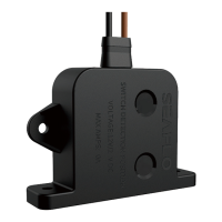
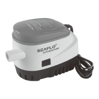
Explains how the float switch activates the pump based on water level.

Manual Bilge Pump Operation

Details manual pump operation without automatic float switch function.

Warning Instructions

Power Source and Initial Wiring

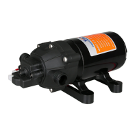
Stresses correct voltage and initial wire connection for pump operation.

Fuse Holder and Wire Splicing

Instructions for splicing fuse holder into the positive lead for safety.

Three-Way Switch Installation and Testing

Describes installing a three-way switch and testing pump operation.

Care and Maintenance

Regular Checks and Cleaning

Advises checking for debris, using the test knob, and cleaning the pump housing.

Impeller Inspection and Electrical Connections

Covers impeller inspection and checking electrical connections for water resistance.

Cleaning Agent Restrictions

Warns against using household cleaners that may damage pump materials.

Security and Safety

Pump Application and Wiring Safety

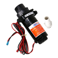
Specifies pump use for water only and correct wiring to battery terminals.

Wire Connection Sealing

Emphasizes sealing wire connections with marine sealant above water level.

Power Disconnection and Fuse Usage

Advises disconnecting power during installation and using the correct fuse amperage.

Pump Mounting Instructions

Float Support Removal

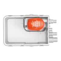
Instructions to remove foam block supporting the float during shipping.

Filter Installation Requirements

Notes on correct filter installation and prohibition of removal during operation.

Pump Placement and Drainage Routing

Guidance on selecting the deepest water level location and proper drainage pipe routing.

Strainer Installation Methods

Details on fixing the strainer to different surfaces using screws.

Outlet Hose Connection and Clamping

Connecting a 3/4" or 1-1/8" ID pipe to the outlet nozzle with a clamp.

Wire Connection Best Practices

Advises securing wire ends with insulators to prevent corrosion at the highest position.

Hull Thickness and Plywood Block

Recommends using a plywood block for hulls less than 1/2" thick for secure mounting.

Pump and Outlet Positioning

Guides on positioning the pump level and ensuring the outlet points toward the transom.

Float Level and Water Avoidance

Ensures the float end is level with or above the pump to prevent dry running.

Drilling and Screw Installation

Instructions for drilling pilot holes and driving screws for mounting.

Hose Clamping and Routing

Details on clamping the hose to the pump and thru-hull connector, and routing it upwards.
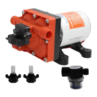
Seaflo 06 Series Specifications

General IconGeneral
Diaphragm MaterialSantoprene
Voltage12V DC
Flow Rate3.0 GPM
Pressure60 PSI
Amps4.5A
Inlet/Outlet1/2" NPT
TypeDiaphragm Pump
Max Flow Rate3.0 GPM
Max Pressure60 PSI
Current Draw4.5A
Inlet/Outlet Size1/2" NPT
Operating Temperature5°F to 140°F

Related product manuals