14.The electrical circuit should be protected with an over-current protection device (fuse) in the positive lead.
This pump requires a 15A @ 12V or 8.5A @ 24V fuse.
11.If applying a sealer or plumbing tape, be careful to not overtighten, as they may be sucked into pump.
16.As the water supply pump is non-essential, reference the wire chart under the electrical information. Be
sure to have the correct wire sizing for the length of wire you are using.
12.This pump should be wired on its own dedicated circuit. Connect the positive lead (red) to the positive
terminal of your battery and the negative wire (black) to the negative terminal of your battery.
13.In an easily accessible location, install a switch to control electricity to the pump. Turn the pump off when
not used for extended periods or when the tank is empty.
15.The pump circuit should not include any other electrical loads.
17.After installation, check the voltage at the pump motor. Voltage should be checked when pump is
operating. Full voltage must be available at the pump motor at all times.
Notes
2.SEAFLO does not recommend the use of metal fittings. When possible, use the provided plastic fittings.
1.Flexible potable water hose or PEX tubing is recommended instead of rigid piping at pump. If you choose
to use rigid piping, provide a short length of hose between pipe and the pump to avoid noise and vibration.
4.Lack of sanitizing and maintenance is one of the main reasons of under performance of the pump. Please
do maintenance and winterize the pump at appropriate times, especially before and after a period of storage.
3.Do not adjust the bypass personally without the help of technician.
ELECTRICAL INFORMATION
Ft.(M)
AWG(MM²)
REPAIR KITS
TROUBLESHOOTING
Quantity
1
1
1
1
1
1
Description
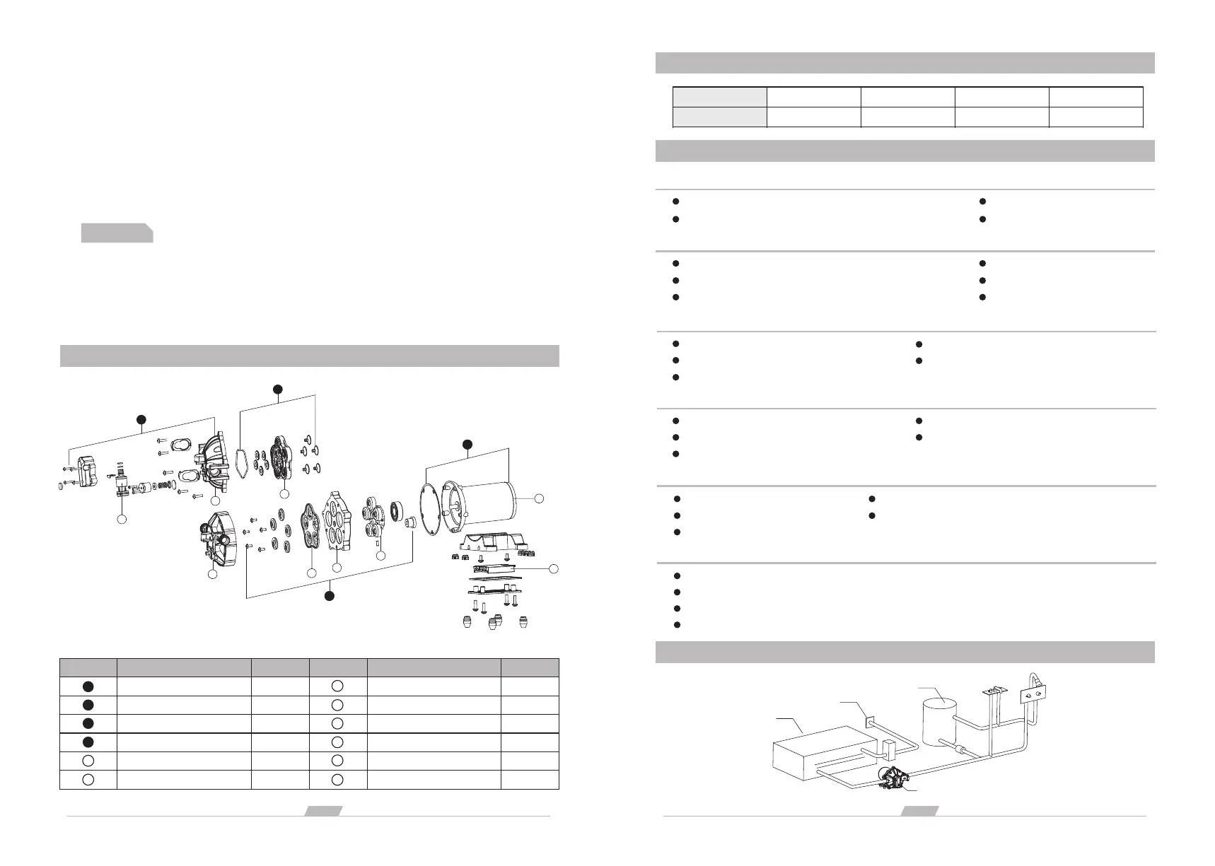
Pump Head Assembly
Valve Assembly
Diaphragm Assembly
Motor Assembly
Pressure Switch
Pump Head
A
B
C
D
Key
1
2
Key
3
4
5
6
7
8
Description
Valve Seat
Motor
Swing Bracket
Diaphragm Base
Diaphragm
Circuit Board Assembly
Quantity
1
1
1
1
1
1
PULSATING FLOW– PUMP CYCLES ON AND OFF
Check lines for kinks.
Clean faucets and filters.
Check fitting tightness for air leaks.
Plumbing lines or fittings may be too small.
MOTOR FAILS TO TURN ON
Pump circuit has no power.
Loose or improper wiring.
Blown fuse.
Failed pressure switch.
Defective motor.
Discharge line leak.
Punctured diaphragm.
Defective pressure switch.
PUMP FAILS TO TURN OFF AFTER ALL FIXTURES ARE CLOSED
Insufficient voltage.
Clogged valves in pump head.
NOISY
Check if the mounting feet are compressed too tightly.
Check for loose head/screws.
Is the mounting surface flexible? If so, it may be adding noise.
If the pump is plumbed with rigid pipe, then it may transmit noise more easily.
FAILURE TO PRIME BUT MOTOR OPERATES - NO PUMP DISCHARGE
Restricted intake or discharge line.
Punctured pump diaphragm.
Initial amp supply is not enough to sufficiently start the motor.
Debris clogged in the valves.
Crack in pump housing.
Air leak in intake line.
LOW FLOW AND PRESSURE
Punctured diaphragm.
Defective motor.
Air leak at pump intake.
Accumulation of debris inside pump or plumbing.
Worn pump bearing (possibly accompanied by loud noise).
3
page
2
page
20-30(6-9)
12 AWG
0-20(0-6)
14 AWG
30-50(9-15)
10 AWG
50-65(15-19)
8 AWG
A
B
C
D
1
3
4
8
5
6
7
USE THE FOLLOWING PROCESS TO ADJUST SHUT-OFF AND BY-PASS PRESSURES
pump
Water tank
Water Inlet Port
Water Heater
2
-56A
2
-56C
 Loading...