Seagate Mobile HDD Product Manual, Rev. D 21
3.3 Drive Mounting
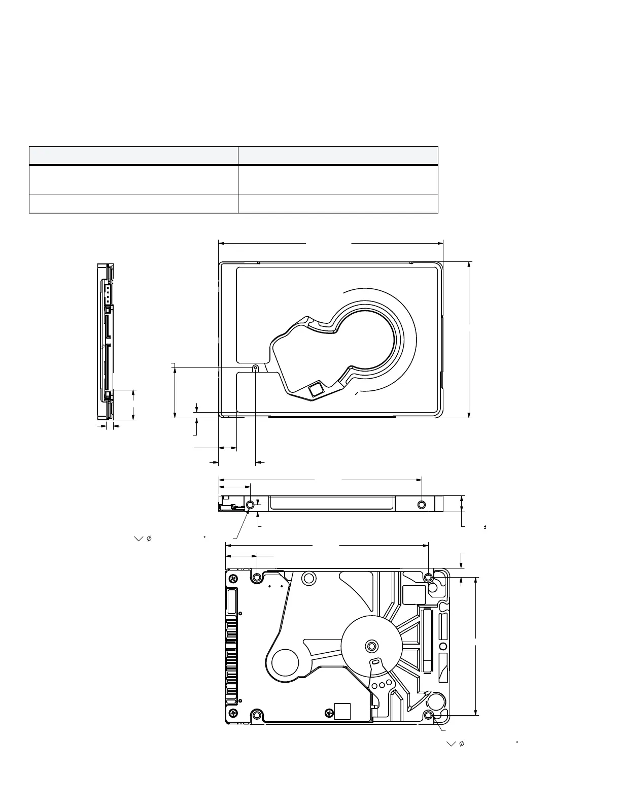
Users can mount the drive in any orientation using four screws in the side-mounting holes or four screws in the bottom-mounting holes. Refer to
Figure 4 and Figure 5 for drive mounting dimensions. Follow these important mounting precautions when mounting the drive:
• Allow a minimum clearance of 0.030 in (0.76 mm) around the entire perimeter of the drive for cooling.
• Use only M3 x 0.5 mounting screws.
• Do not overtighten the mounting screws. Maximum torque: 4.0 in-lb (0.4519 N-m).
• Four (4) threads (0.080 in, 2.032 mm) minimum screw engagement recommended.
• Avoid excessive drive distortion when mounting. Refer to the following specifications for stiffness/deflection information:
Figure 4 Mounting Dimensions (for 1-disk models)
Top cover stiffness/deflection
Operating: no performance degradation, emitted
noise, mechanical damage, or hard errors
10 mm probe: 2.0kgf (typical)
Non-operating: no hard errors 10 mm probe: maximum 2.0kgf (instantaneous)
100.350
+
-
0.200
0.250
69.850±0.250
2.499±1.270
7.949±1.270
(16.520)
(22.450)
(90.600)
(14.000)
2X (3.000)
7.000 0.200
2X M3 X 0.5-6H
MOUNTING HOLES: BOTH SIDES
MIN 3MM FULL THD
3.505+.075-.3X90
(61.720)
(4.070)
(90.600)
(14.000)
4X M3 X 0.5-6H
MIN 2.5MM FULL THD
3.505+.075-.3X90
(13.430)
(3.0)
BASE
BOTH SIDES
BASE