INSTALLATION
MANUAL
Section 2: ELECTRICAL INSTALLATION
2.1 ELECTRICAL EQUIPMENT CONNECTIONS
Reference Documents & Drawings:
•
90510 – Seakeeper 1 Hardware Scope of Supply
•
90511 – Seakeeper 1 Cable Block Diagram
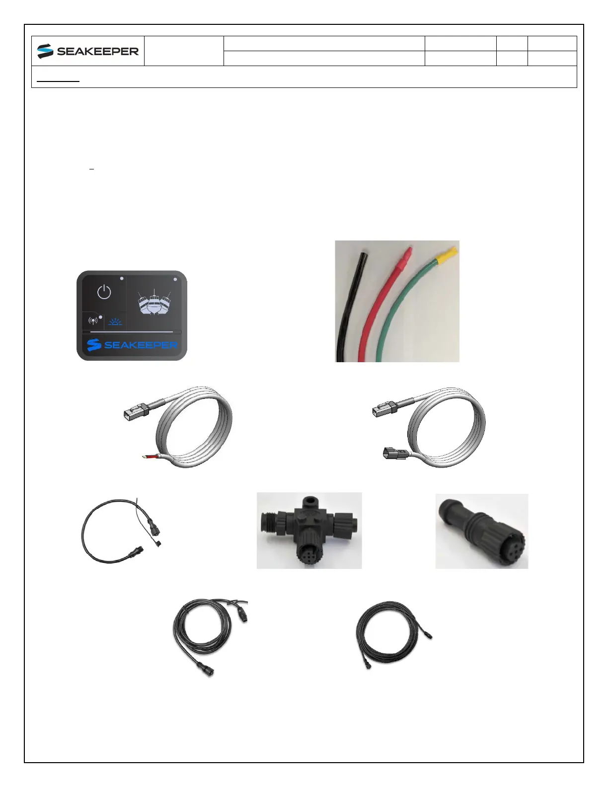
The following figures show the electrical equipment included with the Seakeeper 1 Hardware Scope
of Supply (Dwg No. 90510):
Figure 2: ConnectBox Figure 3: Cable 1 & 2, 2AWG, 12VDC Input / Cable 6, 4AWG Ground
Figure 4: Cable 7, 2x16AWG, Pump Pwr Input Figure 5: Cable 5, 2x16AWG, Pump Pwr Output
Figure 6: Cable 4, CAN, 0.6 m Figure 7: Tee Adapter Figure 8: Terminator
Figure 9: Cable 11, NMEA, 6 m Figure 10: Cable 10, D-Code, 10 m