INSTALLATION
MANUAL
Section 2: ELECTRICAL INSTALLATION
Reversing polarity on the DC power input to the Seakeeper can result in damaging
the electronics in the control system.
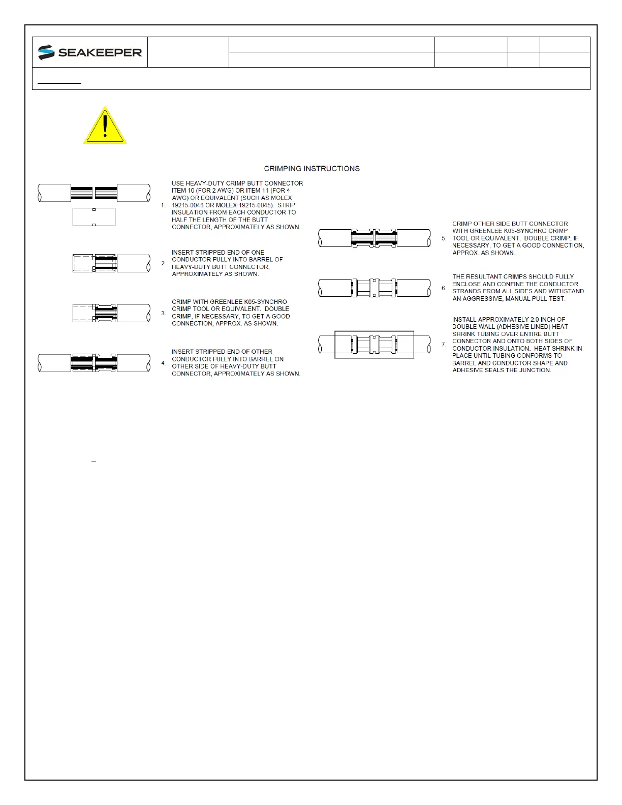
Figure 12: High Current DC Input Crimping Instructions (Dwg no. 90511)
2.3 SEAWATER PUMP CONNECTION INSTRUCTIONS
Reference Documents & Drawings:
•
90511 – Seakeeper 1 Cable Block Diagram
•
90512 – Seakeeper 1 Cooling Water Schematic
2.3.1 SEAWATER PUMP 12 VDC POWER SOURCE REQUIREMENTS
1. Power Source: Battery Bank, 12 VDC, Marine, Deep Cycle
2. Voltage Range: 10 – 16 VDC
3. Current Rating: Max 15A rating
4. Overcurrent Protection: Per pump specification, max 15A
2.3.2 SEAWATER PUMP 12 VDC POWER INPUT CONNECTION INSTRUCTIONS
5.
1. Connect CABLE 7 (P/N: 30327) to Seakeeper 1 “SW Pump DC In” as shown in Drawing No. 90511
with overcurrent protection corresponding to seawater pump selected.
2. Connect the 14AWG plus conductor (red) through dedicated overcurrent protection device
(customer-supplied), maximum of 15A, to dedicated battery isolation switch.
a. The CABLE 1, 2AWG B+ conductor (red), is capable of carrying the current for both the High
Current and Seawater Pump from the 12VDC power supply to the battery isolation switch.
3. Connect the 14 AWG minus conductor (black) directly to battery minus terminal or DC main
negative bus.
 Loading...


