INSTALLATION
MANUAL
Product: Document #: Rev: Page:
SEAKEEPER 6 90402 1 3 of 6
Section 2: ELECTRICAL INSTALLATION
2.2 Electrical Equipment Power Connections
1. AC INPUT POWER SOURCE REQUIREMENTS
a. Either of two AC input voltages are acceptable:
i. 110 VAC (nominal), 1 Phase, 50/60 Hz, 25 Amps.
ii. 230 VAC (nominal), 1 Phase, 50/60 Hz, 20 Amps.
b. A separate circuit breaker should be used for each Seakeeper Drive Box.
c. Seawater pumps must be rated at 110 or 230 VAC, consistent with the AC input
voltage used, and must be 5 Amps max.
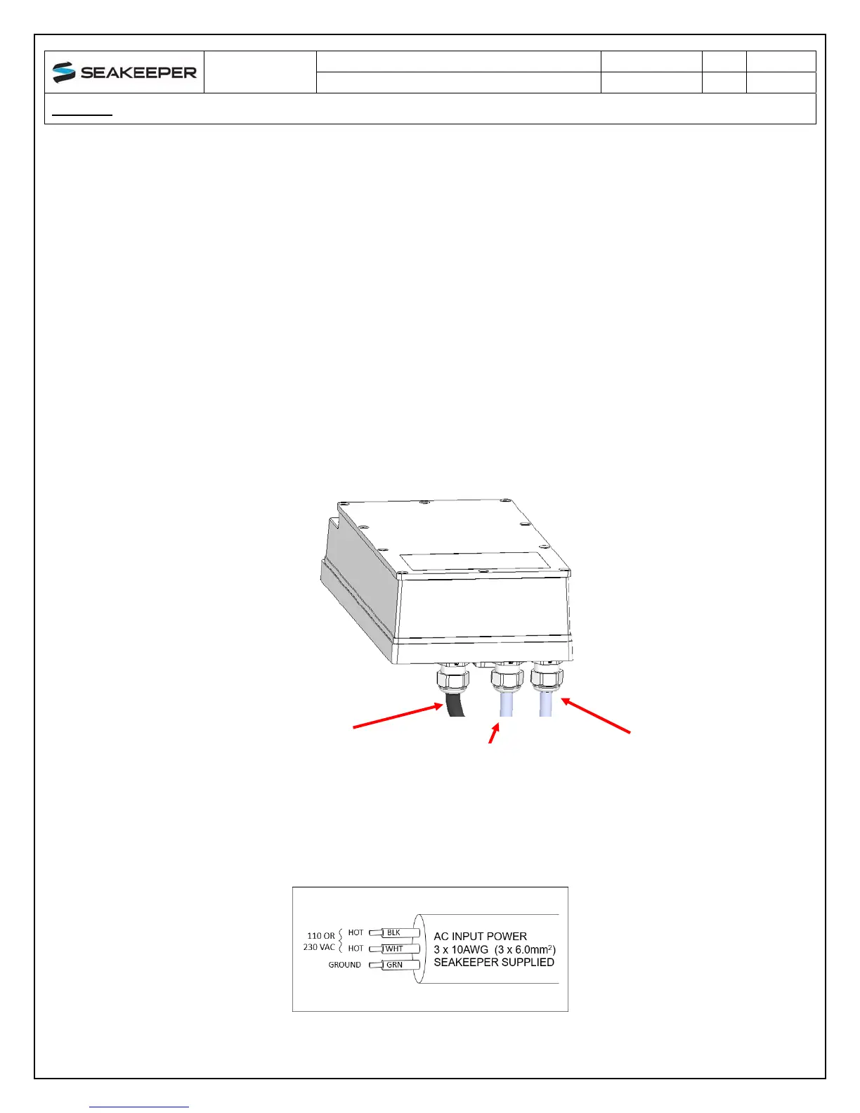
2. DRIVE BOX AC POWER INPUT CONNECTION INSTRUCTIONS
a. Cable: 3 x 10AWG (3 x 6mm
2
CSA), 10’ (3m) length, Seakeeper supplied pre-
installed.
i. Locate CABLE 2 for AC power input to the Drive Box at the outward of three
cable glands.
FIGURE 2 – DRIVE BOX AC POWER INPUT & OUTPUT CABLE GLANDS
FIGURE 3 – CABLE 2 WIRE CONNECTIONS AT AC POWER DISTRIBUTION PANEL
OUTWARDCABLEGLANDFOR
ACPOWERINPUT
(CABLE2)
MIDDLECABLEGLANDFORAC
POWEROUTPUTTO
SEAWATERPUMP(CABLE5)
INWARDCABLEGLANDFOR
DRIVEPOWEROUTPUTTO
SEAKEEPERMOTOR
 Loading...