INSTALLATION
MANUAL
Product: Document #: Rev: Page:
SEAKEEPER 6 90402 1 4 of 6
Section 2: ELECTRICAL INSTALLATION
ii. Connect AC input conductors in CABLE 2 to a double-pole Circuit Breaker at
an AC power distribution panel according to Figure 3 above.
1. 110 VAC, 25 Amp circuit breaker
2. 230 VAC, 20 Amp circuit breaker
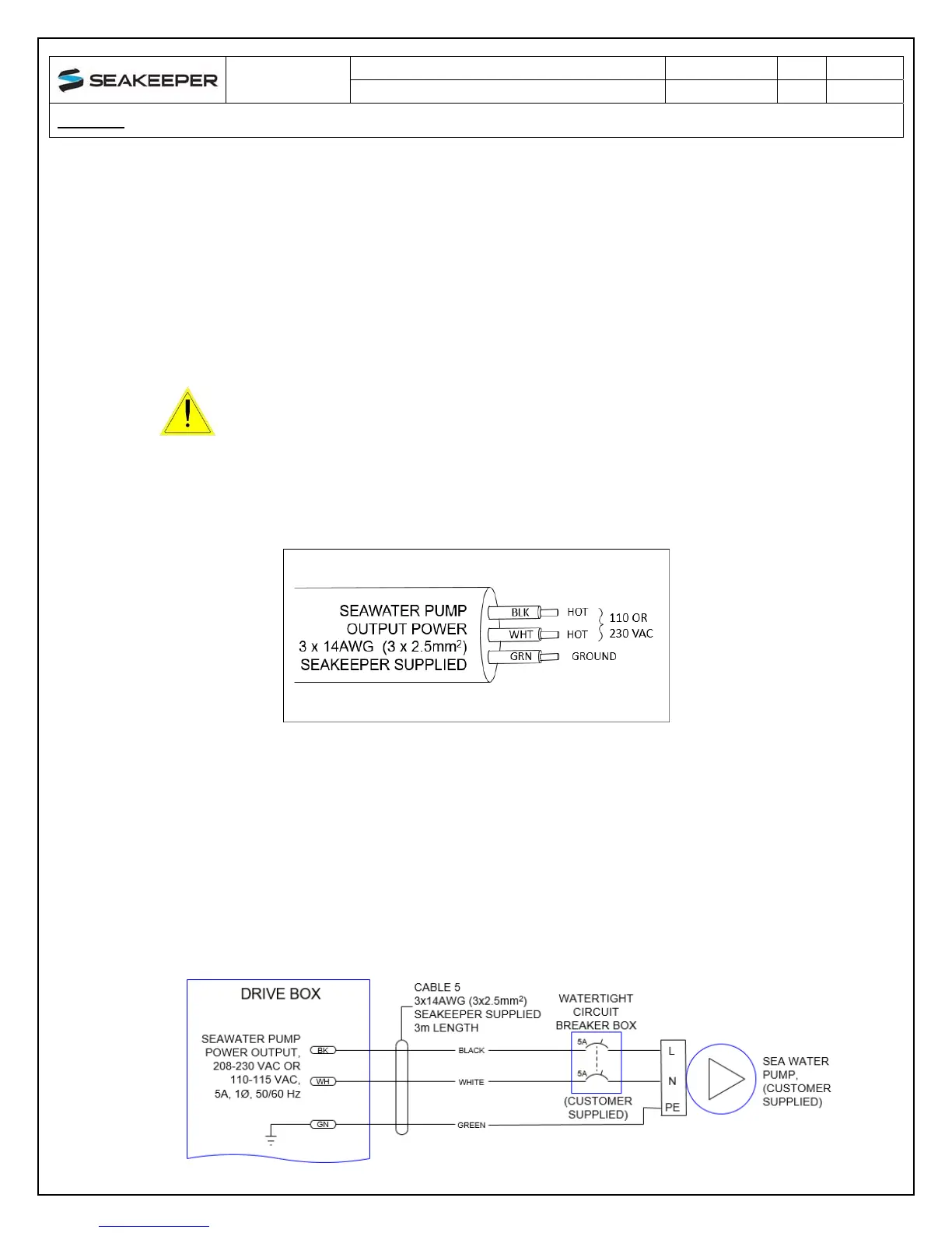
3. DRIVE BOX AC POWER OUTPUT TO SEAWATER PUMP CONNECTION
INSTRUCTIONS
a. Locate CABLE 5 for AC power output to the Seawater Pump from the Drive Box at
the middle of three cable glands. (See Figure 2.)
FIGURE 4 – CABLE 5, AC OUTPUT POWER CABLE
b. Connect the AC output conductors in CABLE 5 to a 5 Amp maximum, Seawater
Pump according to Figures 4 and 5.
i. Pumps must be rated at 110 or 230 VAC, 5 Amps max., Customer-supplied.
ii. The customer supplied seawater pump must have overcurrent protection with
a rating of 5A, 250 VAC. This protection circuit shall be installed in line with
the seawater pump as shown in the diagram below.
FIGURE 5 – CABLE 5, WIRE CONNECTIONS TO SEAWATER PUMP
VerifythatACpowerisOFFtotheDriveBoxbeforeconnecting
CABLE5toaSeawaterPump.
 Loading...