INSTALLATION
MANUAL
Product: Document #: Rev: Page:
SEAKEEPER 6 90402 1 5 of 6
Section 2: ELECTRICAL INSTALLATION
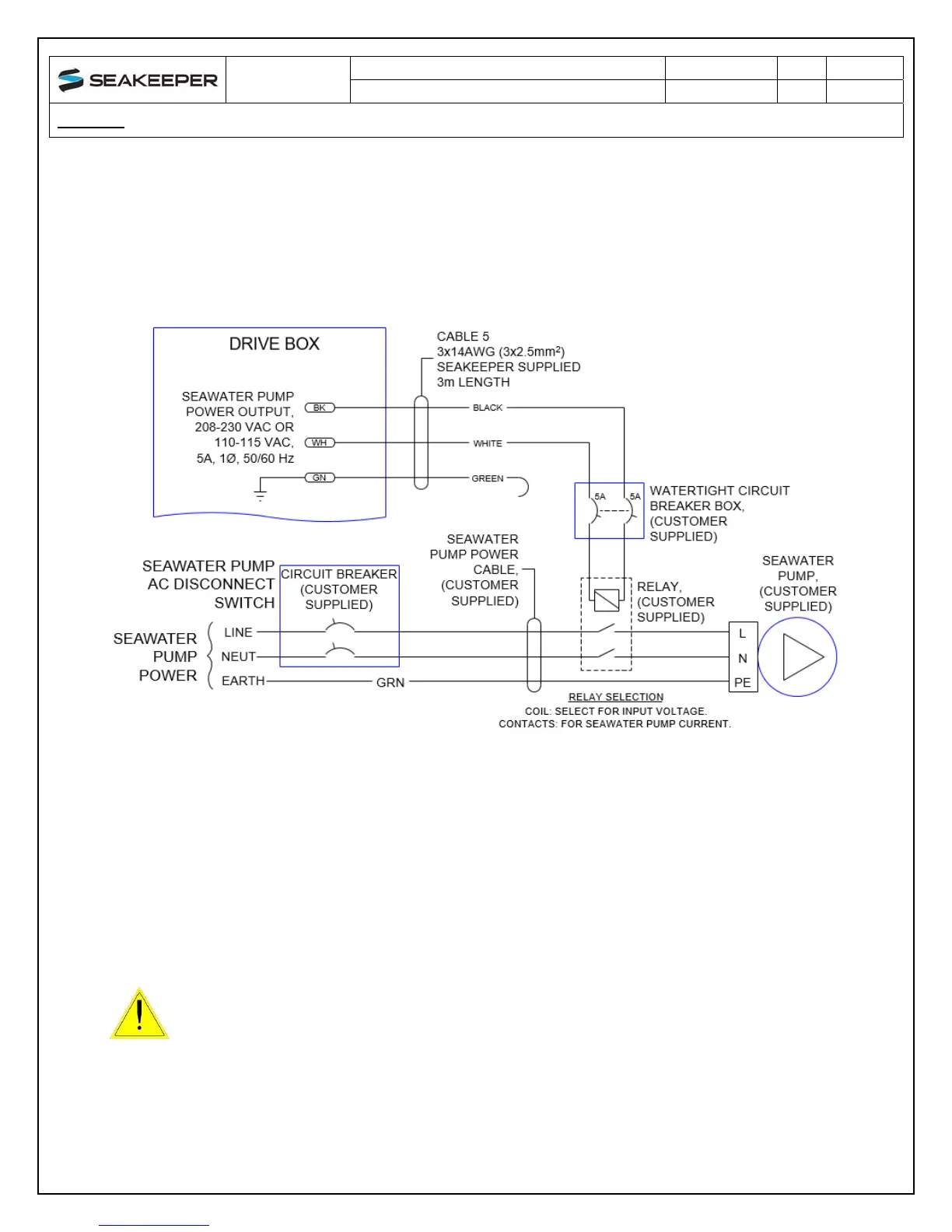
c. If the customer-supplied Seawater Pump is not rated for the applied AC input voltage,
the CABLE 5 output may be used to switch a customer-supplied relay.
i. Locate CABLE 5 for AC power output to the Seawater Pump from the Drive Box
at the middle of three cable glands as shown in Figure 2.
ii. The recommended wiring is shown in Figure 6. Refer to Figure 4 for Cable 5
wire connections.
FIGURE 6 – RECOMMENDED WIRING FOR SEAWATER PUMPS NOT MATCHING INPUT
AC VOLTAGE
d. If CABLE 5 is not used, bundle cable and secure to forward brace or other area
nearby which will not come in contact with moving parts during Seakeeper operation.
Do NOT cut CABLE 5 as it contains live voltage when Seakeeper is in operation.
Seakeeper ships with CABLE 5 permanently sealed at end of cable with protective
cap in the event it is not used. Do NOT remove CABLE 5 from Drive Box as moisture
will be free to enter box through open cable gland and corrode internal electronic
components.
4. 12 VDC POWER SOURCE REQUIREMENTS
a. 12 VDC, 15 Amps.
b. A separate breaker should be used for each Seakeeper.
Cable 5 contains live voltage when Seakeeper is in operation. Do
NOT cut Cable 5. Do not remove Cable 5 from Drive Box.
 Loading...