OPERATION
MANUAL
Product: Document#: Rev: Page:
MODEL8000GYRO 90141 3 4of11
Section1:SYSTEMOVERVIEW
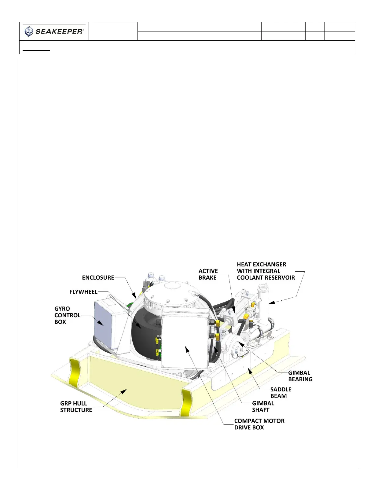
1.1 GyroAssembly
The gyro assembly consists of a flywheel housed in a cast aluminum vacuum‐tight enclosure.The
flywheel spins about a vertical axis and is supported by upper and lower pairs of bearings.A DC
brushlessmotormountedinsidetheenclosurespinstheflywheelathighspeed.
The enclosure is fastened to
two gimbal shafts that are supported by gim bal bearings on either side.
These shafts establish an athwartship gimbal axis about which the flywheel and enclosure precess or
rotateupto+/‐60degreesduringoperation.Eachofthegimbalbearingsissupportedbyasaddlebeam
whichisbondedto
thehullstructure.Thesebeamstransfertheloadsthatthegyroproducestothehull
structure.
Anactivehydraulicbrakemechanismislocatedonthegyro assemblytoregulatethegyro’sprecession
motionsaboutthegimbalshaft.Itincludestwohydrauliccylindersmountedonthebrakesaddlebeam
andahydraulic
manifoldonthenon‐brakesaddlebeam.
Acoolantpump,heatexchangerwithreservoir,andther mostaticmixingvalvearelocatedonthebrake
saddle beamnear the hydraulic cylinders.Braces forward andaft ofthe enclosure connect the brake
andnon‐brakesaddlebeams.Aglycol/watermixiscirculatedthru
aclosedlooptothemotordrivebox,
hydraulicmanifold,andtheendcapsoftheenclosuretoremoveheat.
FIGURE3–GYROASSEMBLY


 To Next Page
 Loading...