3. CHARGING INSTRUCTIONS
2. INTRODUCTION & SPECIFICATIONS
3.1. Preparation
It is important to correctly prepare for charging, ensuring that you follow Section 1 safety instructions carefully. Check that the capacity
of the battery is compatible with the charger output. Charging current (amps) should not exceed one tenth of the value of the battery
capacity (amp hours).
3.1.1. Follow the vehicle manufacturer’s instructions for charging the battery. Note special instructions for charging vehicle batteries in situ.
3.1.2. Check the battery to ensure that the POSITIVE and NEGATIVE terminals are clearly identifiable before removing the battery from the
vehicle.
3.1.3. Subject to 3.1.1. above, disconnect and remove the battery from the vehicle and place in an appropriate safe area ready for charging.
3.1.4. If possible, remove the battery electrolyte cover or caps to allow the gases produced by charging to escape.
3.1.5. Check that the electrolyte is covering the plates inside. If not, add distilled water so that the plates are covered by 5-10mm.
3.1.6. The charge status of the battery may be determined by use of a hydrometer to measure the specific gravity (relative density) of the
electrolyte: 1.28 = Fully charged 1.21 = Half charged 1.14 = Fully discharged.
WARNING! Be cautious and vigilant - the electrolyte is a highly corrosive acid.
3.2. Connecting the charger to the battery. Ensure that the battery charger is unplugged from the mains power supply before connecting
the leads to the battery.
3.2.1. Select the charger voltage to match that of the battery by setting the rocker switch to either 12 or 24 volts.
3.2.2. Initially, always set the Charge Rate rocker switch to 'MIN'.
3.2.3. Check that the charger clamps and battery terminals are clean and free from oxidation.
3.2.4. Connect the chargers POSITIVE (red) lead to the POSITIVE (+) terminal on the battery, and the NEGATIVE (black)
lead to the NEGATIVE (-) terminal on the battery.
3.3. Charging the battery
3.3.1. Connect the charger to the mains power supply and turn it on with the front panel mounted ON/OFF switch.
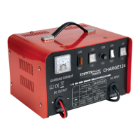
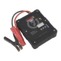
3.3.2. Check the current delivery to the battery by reading the ammeter on the front of the battery charger. During charging
the pointer on the ammeter will slowly move to the left according to the capacity and condition of the battery (see fig.1, meter
face may vary according to model).
3.3.3. If a boost charge is required, ensure that an initial charge has built up first before moving the Charge Rate rocker switch to 'BOOST'.
3.3.4. To indicate that the battery is fully charged the reading on the ammeter should be at the “0” output indicator. To correspond with
this the electrolyte in the battery will begin to gas. Stop charging at this point in order to protect the battery plates from damage.
1.3. PERSONAL PRECAUTIONS
Ensure that there is another person within hearing of your voice and close enough to come to your aid,
should a problem arise when working near a lead-acid battery.
Wear safety eye protection and protective clothing. Avoid touching eyes while working near battery.
Have fresh water and soap nearby in case battery acid contacts skin, clothing, or eyes.
Wash immediately with soap and water if battery acid contacts skin or clothing. If acid enters eye, flush eye immediately with cool, clean
running water for at least 15 minutes and seek immediate medical attention.
Remove personal metallic items such as rings, bracelets, necklaces and watches. A lead-acid battery can produce a short-circuit current
high enough to weld a ring to metal, which would cause severe burns.
Ensure that hands, clothing (especially belts) are clear of fan blades and other moving or hot parts of the engine. Remove ties and contain
long hair.
DO NOT smoke or allow a spark or flame in the vicinity of battery or engine.
This appliance is not intended for use by persons (including children) with reduced physical, sensory or mental capabilities or lack of
experience and knowledge, unless they have been given supervision or instruction concerning the use of the appliance by a person responsible
for their safety. Children should be supervised to ensure that they do not play with the appliance.
DANGER! BE AWARE, LEAD-ACID BATTERIES GENERATE EXPLOSIVE GASES DURING NORMAL BATTERY OPERATION. FOR THIS
REASON, IT IS VERY IMPORTANT TO READ AND FOLLOW THESE INSTRUCTIONS CAREFULLY, EACH TIME YOU USE THE CHARGER.
Follow these instructions and those published by the battery and vehicle manufacturers and the manufacturer of any equipment
you intend to use in the vicinity of the battery. Remember to review warning marks on all products and on engines.
DO NOT allow the charger terminal clamps to touch each other when the power is on or the charger fuse will blow. Remember that gases
are produced which may ignite if sparks occur.
DO NOT get the charger wet or use in damp or wet locations or areas where there is condensation.
DO NOT operate the charger if it is damaged.
DO NOT attempt to modify or open the charger.
When not in use, unplug from the mains power supply and store in a safe, dry, childproof area.
WARNING! Be vigilant and cautious during battery charging as the electrolyte is highly corrosive and the emitted gases are explosive.
fig.1
Original Language Version
CHARGE106,107,110,112,115,124 Issue: 1 - 16/04/12
MODEL No. CHARGE106 CHARGE107 CHARGE110 CHARGE112 CHARGE115 CHARGE124
Rated charging current: 6A 7A 10A 12A 15A 24A
Maximum charging current (Boost): 8A 11A 14A 16A 19A 28A
Charging capacity: 10-95Ah 20-105Ah 20-120Ah 20-200Ah 20-250Ah 25-320Ah
Volts Output: 12/24V 12/24V 12/24V 12/24V 12/24V 12/24V
Volts Input: 230V 230V 230V 230V 230V 230V
Watts Input: 100W 150W 200W 200W 700W 1000W
Charging Rates: 2 2 2 2 2 2
Polarity protection Fuse (1 x 15A) Fuse (1 x 15A) Fuse (1 x 20A) Fuse (1 x 30A) Fuse (1 x 30A) Fuse (1 x 40A)
Input Protection Fuse T3A T3A T4A T5A T5A T6A
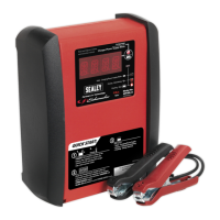
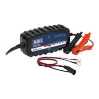
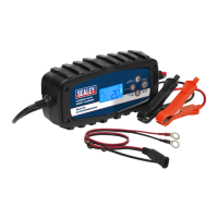
Supplied in steel case with carry handle, these single phase chargers feature plenty of ventilation to help maintain low transformer temperatures.
A large ammeter displays rate of charge and a dash-mounted fuse provides polarity protection in the event that clips are connected incorrectly.
Rocker switches control variable output to the battery to maintain peak condition. Suitable for regular and low maintenance batteries. Supplied
with 2200mm length output cables with heavy-duty crocodile clips and are tted with ASTA/BS approved non-rewirable 3-pin safety plug.
 Loading...