4. CONTENTS
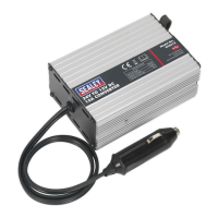
System Component Identification:
1 Blackbatteryclamp(NEG-) 6 PowerLead
2 Redbatteryclamp(POS+) 7 BlackClip(Sensorlead)
3 Pick-uploop 8 YellowClip(Sensorlead)
4 IndicatorLight 9 Sensorlead
5 Piezo clamp (diesel sensor)
5. SET UP & OPERATIONt
5.1. Youmustuseamonitoringdevicesuchasatiminglight,engineanalyser
ormultimeterinconjunctionwiththedieselconverterboxinordertobeable
to read RPM on the device’s display. The most common use for this
information will be for setting a constant engine speed for diesel engine
smoke testing. Remember to set up your monitoring device for the correct
number of cylinders.
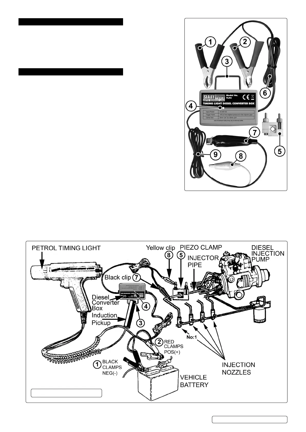
5.2. Ensure that the vehicle ignition is off. Locate the fuel pipes connecting the
pumptothefuelinjectors.ForenginetimingpurposesthePiezoClamp
should be attached to the pipe going to the No.1 cylinder.
5.3. FixthePiezoClamp(5)ontoastraightsectionoftheInjectorfuelpipefor
the No.1 cylinder as close to the pump as possible in order to get the
strongest reading. The Piezo Clamp and fuel pipe should be clean and dry.
Make sure that the Piezo Clamp is in full contact with the fuel pipe but
DO NOT overtighten as this could cause damage to the sensor within the clamp.
5.4. TaketheSensorLeadandconnecttheYELLOWclip(8)tooneofthe
adjustablefixingsontheclampandtheBLACKclip(7)tothesameInjector
fuel pipe to which the clamp is connected.
WARNING! Ensure that the Black Sensor clip DOES NOT touch any of the
Glow Plugs and associated mountings or wiring as this may cause a short
circuit which could disable engine operation and may damage any connected
monitoring device.
5.5. Take the Power Lead and connect the RED clamp (2) to the positive side of the vehicle battery and the BLACK clamp (1) to
the negative of the battery. Note: The monitoring device used i.e. A Timing Light, Engine Analyzer or Digital Multimeter may also
be powered from the vehicle’s battery.
5.6. Attach the inductive pickup from your chosen monitoring device e.g. a timing light, onto the Pickup Loop (3) on the converter box. If the
timing light inductive pickup has an arrow mark, ensure that the mark is face up when attached to the Pickup Loop.
5.7. Start the engine and allow it to reach operating temperature, then read the results from the timing light. The Indicator Light on the
converterbox(4)shouldflashconsistently.Iftheindicatorlightdoesnotflash,checkalltheconnectionsorrelocatethePiezo
Clamptoanothersectionofthefuelpipe.Note:Lowvehiclebattery,defectiveInjectorPump,orlackoffuelmaypreventtheIndicator
Light from flashing.
OPERATION DIAGRAM
TL95|Issue:2(L)29/09/17
Original Language Version
© Jack Sealey Limited
 Loading...