115 VOLT OPERATION
This grinder is equipped with a 3-conductor cable (for 115
volt operation only) having a fixed grounding conductor.
Receptacle not having provision for the grounding pin will
require a plug adapter as shown in the following
illustration ... available at Sears retail or catalog stores.
WARNING: PROTECT THE OPERATOR AGAINST
ELECTRICAL SHOCKS BY ALWAYS CONNECTING
THE. GROUND WI RE FROM THE ADAPTER TO A
PERMANENT GROUND BEFORE PLUGGING IN
TH E POWER CORD. OPERATION WITHOUT
GROUNDING CAN CAUSE SERIOUS ELECTRICAL
SHOCKS WHICH MIGHT BE FATAL.
This connection can be made to the receptacle cover screw,
IF THE OUTLET BOX IS PROPERLY GROUNDED, or to
another suitable ground such as a water pipe. Never connect
the green wire to a line terminal.
If this grinder is not required to start under load and is not
overloaded after starting, the standard 15 ampere lighting
circuit fuses should be satisfactory. Otherwise, a
"delayed-action" type fuse designed to meet the demands
of motor protection and minimize possible nuisance of
"blown" fuses from momentary overloading.
~~~D
GroundWire/
I ~
This grinder will start and operate on a 115 volt lighting
circuit. Use a 15 ampere fuse.
Replace a damaged or worn cord immediately.
If necessary to use an extension, use only 3-wire cords
which have, 3-prong grounding type plugs and 3-pole
receptacles which accept the tool's plug. The following
chart of lengths and wire sizes must be followed for safe
operation.
Length of
Extension
Wire Size Required
(American Wire Gauge No.)
15 feet or less
50 feet or less
100 feet or less
No.14
No.12
No.10
230 VOLT (SINGLE PHASE) OPERATION:
Use a 230 volt, 50 watt "rough service" bulb (G.E. 50
AIRS equivalent.)
To reconnect grinder for 230 volt operation, the following
steps must be taken:
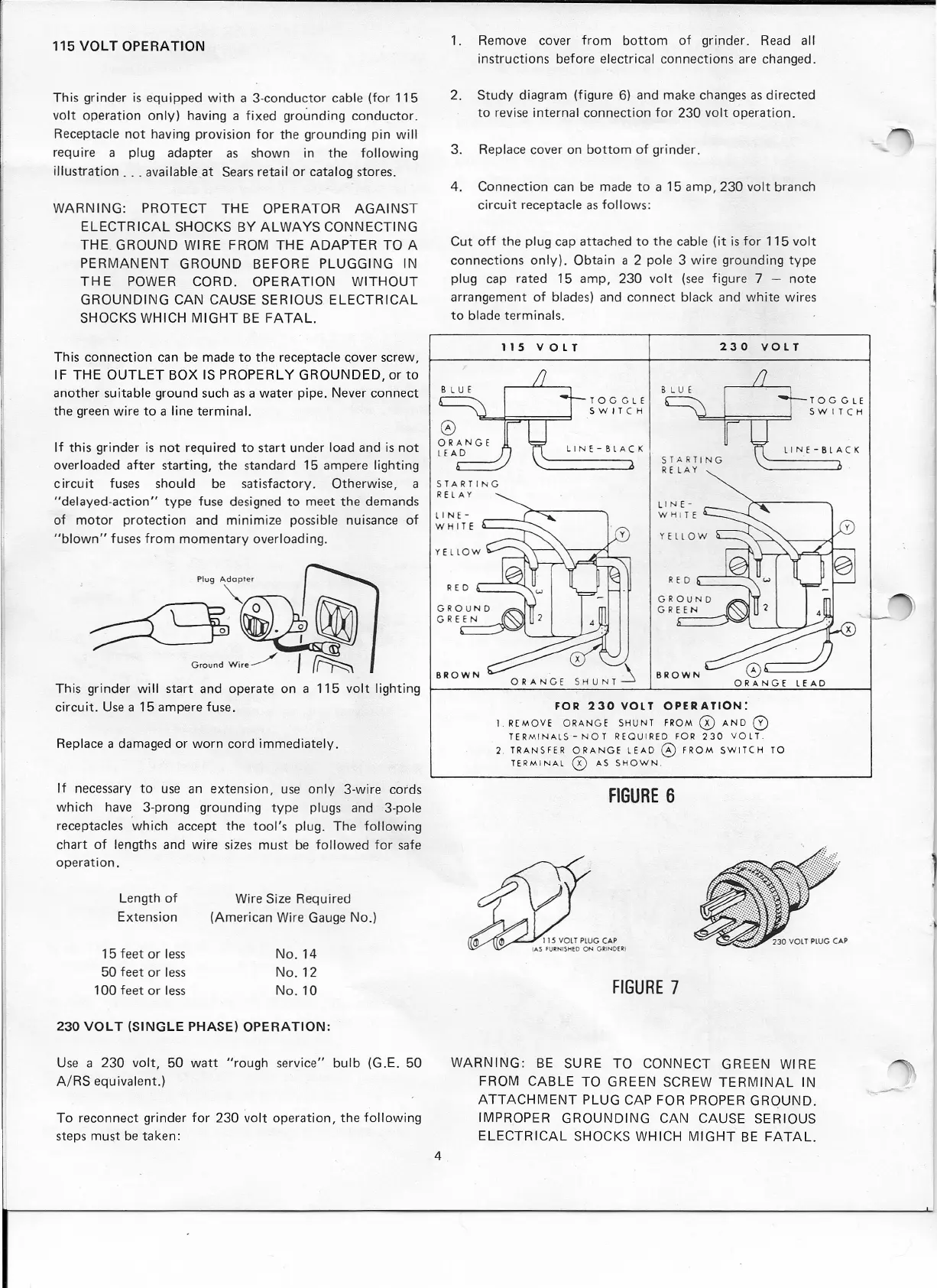
1. Remove cover from bottom of grinder. Read all
instructions before electrical connections are changed.
2. Study diagram (figure 6) and make changes as directed
to revise internal connection for 230 volt operation.
3. Replace cover on bottom of grinder.
4. Connection can be made to a 15 amp, 230 volt branch
circuit receptacle as follows:
Cut off the plug cap attached to the cable (it is for 115 volt
connections only). Obtain a 2 pole 3 wire grounding type
plug cap rated 15 amp. 230 volt (see figure 7 - note
arrangement of blades) and connect black and white wires
to blade terminals,
230 VOLT
TOGGLE
SWITCH
115 VOLT
TOGGLE
SWITCH
LINE-BLACK
STARTING
R E LA Y
LINE-BLACK
STARTING
R E
LAY
II
N E-
WH
I T E
L IN E-
W
HI
T E
RED
~--'--=-I..
GROUND
G R E E N
BROWN
x
~ BROWN
ORANGE SHUNT LEAD
FOR 230 VOL TOPER ATION:
I REMOVE ORANGE SHUNT FROM
0
AND
0
TERMINALS - NOT REOUIRED FOR 230 VOL T.
2 TRANSfER ORANGE LEAD
0
fROM SWITCH TO
TERMINAL
0
AS SHOWN.
FIGURE 6
FIGURE 7
WARNING: BE SURE TO CONNECT GREEN WIRE
FROM CABLE TO GREEN SCREW TERMINAL IN
ATTACHMENT PLUG CAP FOR PROPER GROUND.
IMPROPER GROUNDING CAN CAUSE SERIOUS
ELECTRICAL SHOCKS WHICH MIGHT BE FATAL.
4
--
 Loading...