EasyManua.ls Logo

Sears 721.66339 User Manual

Sears 721.66339
39 pages
To Next Page IconTo Next Page
Page #1 background imageLoading...
Page #1 background image
DIVISION 20
BASIC FIELD MANUAL
FOR
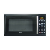
MICROWAVE OVEN
MODEL 721.66339800
February, 2008
MODEL 721.66339

Questions and Answers:

Sears 721.66339 Specifications

General IconGeneral
CategoryMicrowave Oven
Model Number721.66339
Power1000 Watts
Child LockYes
DisplayLED
Cooking ModesDefrost, Reheat, Popcorn, Potato

Summary

CAUTION WARNING TO SERVICE TECHNICIANS

FOREWORD

MECHANICAL SERVICE INFORMATION

1. ADJUSTMENT PROCEDURES

CHECK THE DOOR LATCH AND SWITCH CLOSING.

Checks door latch and switch closing for proper alignment and gaps.

ADJUST THE LATCH AND SWITCH CLOSING

Adjusts latch board for proper alignment and gap closure.

TEST THE LATCH AND SWITCH SEQUENCE

Tests primary, secondary, and monitor interlock switch sequence.

TEST THE MICROWAVE ENERGY LEAKAGE

Measures microwave energy leakage using a survey meter after adjustments.

2. PRECAUTIONS ON INSTALLATION

3. GENERAL PRECAUTIONS IN USE

4. TRIAL OPERATION

5. FEATURES AND SPECIFICATIONS

SPECIFICATIONS

SWITCH TABLE

Details switch modes and continuity results for door open/closed states.

6. OVERALL CIRCUIT DIAGRAM

A. SCHEMATIC DIAGRAM

Presents the overall schematic diagram of the microwave oven's electrical system.

B. MATRIX CIRCUIT FOR TOUCH KEY BOARD

Displays the matrix circuit layout for the microwave's touch control keyboard.

7. OPERATING PROCEDURES

A. OVEN CONTROL PANEL

Explains layout and function of each key and display element on the control panel.

B. EASY USE TABLE

Provides a simplified table for easy operation of various microwave functions.

8. PROCEDURE FOR MEASURING MICROWAVE ENERGY LEAKAGE

A. CAUTIONS

Safety warnings and considerations before and during microwave energy leakage measurement.

B. MEASURING MICROWAVE ENERGY LEAKAGE

Step-by-step guide for measuring microwave energy leakage using equipment.

C. MEASUREMENT WITH THE OUTER CASE REMOVED

Specific procedures for measuring leakage with the oven's outer case removed.

D. MEASUREMENT WITH A FULLY ASSEMBLED OVEN

Instructions for measuring microwave leakage on a fully assembled oven.

E. NOTE WHEN MEASURING

Important notes and tips for accurate microwave leakage measurement.

F. RECORD KEEPING AND NOTIFICATION AFTER MEASUREMENT

Guidelines for recording and reporting microwave leakage test results.

G. POWER OUTPUT MEASUREMENT

Procedure to measure microwave oven's power output using a water load.

9. DISASSEMBLY INSTRUCTIONS

A. REMOVING OUTSIDE CASE

Step-by-step guide to remove the outer case of the microwave oven.

B. REMOVING POWER AND CONTROL CIRCUIT BOARD

Instructions for removing the power and control circuit boards.

C. DOOR ASSEMBLY / REMOVAL

Procedure for disassembling or removing the microwave oven door.

D. MAGNETRON REMOVAL

Detailed steps for safely removing the magnetron assembly.

E. REMOVING THE TURNTABLE MOTOR

Instructions on how to remove the turntable motor and its components.

F. HIGH VOLTAGE TRANSFORMER REMOVAL

Steps to remove the high voltage transformer, including capacitor discharge.

G. FAN MOTOR ASSEMBLY / REMOVAL

Guide for removing the fan motor assembly and related components.

H. HIGH VOLTAGE CAPACITOR AND DIODE REMOVAL

Procedure for removing the high voltage capacitor and diode.

I. REMOVING SENSOR

Instructions for removing the sensor components from the oven.

J. INTERLOCK SYSTEM

1) INTERLOCK MECHANISM

Explanation of the door lock mechanism preventing microwave activity when the door is open.

2) MOUNTING OF THE PRIMARY/MONITOR/SECONDARY SWITCHES TO THE LATCH BOARD

Procedure for mounting interlock switches onto the latch board.

3) INSTALLATION AND ADJUSTMENT OF THE LATCH BOARD TO THE OVEN ASSEMBLY

Steps for installing and adjusting the latch board assembly.

10. INTERLOCK CONTINUITY TEST

A. PRIMARY INTERLOCK SWITCH TEST

Tests continuity of the primary interlock switch for proper operation.

B. SECONDARY INTERLOCK SWITCH TEST

Tests continuity of the secondary interlock switch for proper operation.

C. MONITOR SWITCH TEST

Tests continuity of the monitor switch for proper operation.

11. TEST AND CHECKOUT PROCEDURES, AND TROUBLESHOOTING

A. TEST PROCEDURES

Procedures for testing various components like transformers and magnetrons.

B. CHECKOUT PROCEDURES

Procedures for troubleshooting common issues like fuse blowing.

(1) CHECKOUT PROCEDURES FOR FUSE BLOWING

Troubleshooting steps for problems related to fuse blowing.

(2) CHECKOUT PROCEDURES FOR RELAY

Troubleshooting steps for issues related to oven relays.

(3) CHECKOUT PROCEDURES FOR CIRCUIT BOARD

Symptoms indicating a defective circuit board and troubleshooting steps.

C. TROUBLE SHOOTING

General troubleshooting guide for common microwave oven problems.

(TROUBLE 1) VISUAL CONDITIONS FOR DEFECTIVE CONTROL CIRCUIT

Identifies visual symptoms suggesting a faulty control circuit board.

(TROUBLE 2) OVEN DOES NOT OPERATE OR ACCEPT INPUT

Troubleshooting steps when the oven is completely unresponsive.

(TROUBLE 3) OVEN DOES NOT START COOKING

Diagnosing why the oven fails to start cooking after settings are entered.

(TROUBLE 4) LOW HEAT PRODUCTION

Troubleshooting low heat output during oven operation.

(TROUBLE 5) NO MICROWAVE OSCILLATION

Diagnosing lack of microwave oscillation when other components are running.

EXPLODED VIEW

DOOR PARTS

CONTROLLER PARTS

OVEN CAVITY PARTS

LATCH BOARD PARTS

INTERIOR PARTS

BASE PLATE PARTS

SENSOR PARTS

Related product manuals