Do you have a question about the Sears 721.67909600 and is the answer not in the manual?
Key safety measures to prevent excessive microwave energy exposure during servicing.
Details the switch modes and their corresponding states for operation.
Information regarding potential hazards from microwave radiation during operation.
Warnings about handling high-voltage components and electrical discharge.
Mandatory procedures for proper grounding of the appliance for safety.
Detailed description of each button and its function on the control panel.
Covers clock setting, start/pause, timer, child lock, warm hold, and time adjustments.
Details on Micro Cooking and Multi-Stage Cooking sequences.
Using sensor cook, popcorn, reheat, auto defrost, and express defrost.
Instructions for auto bake/roast, convection, and combination cooking.
Key to understanding wire colors used in the schematic diagram.
Explanation of basic operations like power supply and door switch interlocks.
Details on circuits for start, door opening during cooking, and convection.
List of necessary tools and instruments for servicing the appliance.
Cautions and procedures for testing microwave leakage.
Guidance on measuring leakage with and without the outer case, plus measurement tips.
Requirements for documenting and reporting leakage test results.
General instructions for disassembling the oven for service.
Steps to remove the control panel assembly and the oven door.
Procedures for removing the air duct system and the magnetron.
Steps for removing turntable motor, HV transformer, fan motor, capacitor, and diode.
Guidance on interlock system adjustment and removing motors/heaters.
Steps to remove the sensor from the air tunnel.
Detailed tests for primary, secondary, and monitor interlock switches.
Measuring resistance for the high voltage transformer and magnetron.
Testing HV capacitor resistance between terminals and to case.
Testing the HV diode for shorts, forward bias, and reverse bias.
Procedures for testing fuses, convection heater, thermostat, and fan motor.
Measuring resistance for circulation, turntable, damper motors, and thermistor.
Checking relay continuity for cooking start and convection functions.
Safety steps and common issues like 'Oven does not work' or 'Sparks occur'.
Diagnosing display problems and input/programming errors.
Troubleshooting fuse blow issues and oven startup problems.
Diagnosing why the oven doesn't cook after settings are made.
Diagnosing issues with insufficient heat production during cooking.
Troubleshooting when the microwave generator is not functioning.
Checking transformer, capacitor, diode, and magnetron for oscillation failure.
Troubleshooting convection indicator, heater, motor, and thermistor faults.
Lists the main assembly categories for the exploded view.
Diagrams and part numbers for door components for specific models.
Diagrams and part numbers for control panel components for specific models.
Diagrams and part numbers for the main oven cavity and interior parts.
Diagrams and part numbers for the door latch board and associated switches.
Diagrams and part numbers for various internal components like fans and motors.
Diagrams and part numbers for the base plate and transformer.
Diagrams and part numbers for sensor-related components.
| Model Number | 721.67909600 |
|---|---|
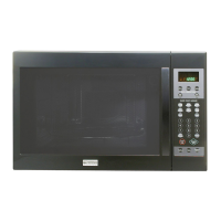
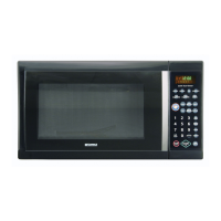
| Category | Microwave Oven |
| Color | White |
| Control Type | Electronic Touch |
| Cooking Modes | Popcorn, Potato, Beverage, Reheat, Defrost |
| Interior Dimensions | 12.4 in (W) x 14.0 in (D) x 8.7 in (H) |