6.
0 1 L PI
VO
T POINTS
Place several drops
of
S.A.E.
30
Oil
at points where
part
.s
move
aga
inst
each
other, especia
lly
:
a.
Fro
nt
Axle
Pivot (Fig. 20).
b. Hood Hinges.
c.
Foot
Pedal
Shaft (Fig.
9).
d.
Lift
Shaft Bushings (Fig. 33).
e.
P
olyf
oam
Seal
at
Variator
Pivot
Shaft (Fig. 16) (saturate
with
oil).
f.
Polyfoam
Seal
(behind
Flat
Idler)
at
Clutch Idler Pivot
Arm
(saturate
with
oil)
{Fig. 16).
g.
Clutch
Link
and Varidrive
Link,
see
page
22
, Key No's.
45an
d47.
h. Vari
dr
i
ve
Handle P
ivot
Bushing (Fig. 33).
EVERY
~@
HOURS
1. C
LEAN
ENGINE
COOLING
FINS
Remove any dust,
dirt
or
oil from Engine Cooling Fins
to
preve
nt
Engine d
amage
from overheating (F ig. 23).
2.
CHECK
TRANSAXLE
OIL
LEVEL
a.
Remove Filler Plug (Fig. 25) from Transaxle. Oil Level
should
be
even
with
F
ill
er Plug threads.
Add
S.A.E.
30
Motor
Oil
if
necessary.
b.
Check
Pressure
Rel
ief
Valve
(F1g.
27 · Inset) located on
R.H. side near top.
It
should spring completely closed
when pulled
out
by
hand
and
released
.
3. L
UB
RICATE
STEERING U-
JOINT
a.
Lih
Hood (Fig. 2).
b. Rotate Steering Wheel so
that
U·Joint
Greas
e
Fitting
is
exposed (Fig. 24).
c.
Using a
Grease
Gun, give
Fitting
two
shots
of
Extreme
Pressure
Lubricating
Grease
Amdex No. 1
or
equivalent
(available at
your
Sears
Service Center).
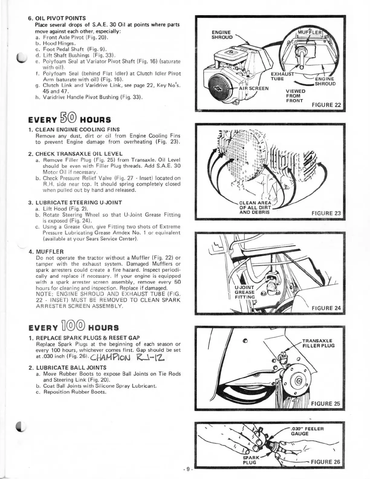
4.
MUFFLER
Do
not
operate the tractor
without
a
Muffler
(Fig. 22)
or
tamper
with
the exhaust system. Damaged
Muff
lers
or
spark arresters could create a fire hazard. Inspect periodi·
cally and replace
if
necessary.
If
your
engine
is
equipped
with
a spark arrester screen assembly, remove every 50
hours
for
cleaning and inspection. Replace
if
damaged.
NOTE: ENGINE SHROUD
AND
EXHAUS
T TUBE (FIG.
22
· INSET) MUST
BE
REMOVED TO
CLEAN
SPARK
ARRESTER SCREEN ASSEMBLY.
EVERY
D@@
HOURS
1. REPLACE
SPARK
PLUGS & RESET GAP
Rep
l
ace
Spark
Plugs
at the beginning
of
each
season
or
every 100 hours, whichever comes first. Gap should be set
at
.030 inch (Fig. 26).
C.HA~Plo~
R-.1-l'Z.
2.
LUBRICATE
BALL
JOINTS
a.
Move Rubber Boots
to
expose Ball Joints on T
ie
Rods
and Steering L
ink
(Fig. 20).
b. Coat Ball Joints with Silicone Spray Lubricant.
c.
Rep
os
ition Rubber Boots.
ENGINE
SHROUD
VIEWED
FROM
FRONT
FIGURE
22
FIGURE
23
FIGURE
24
TRANSAXLE
FIL
LER PLUG
FIGURE
25
another free manual from www.searstractormanuals.com