2.
BRAKE
ADJUSTMENT
IF
TRACTOR
REQUIRES MORE
THAN
SIX
FEET
STOPPING DISTANCE
IN
HIGHEST
GEAR
ON A
LEVEL
DRY
CONCRETE OR
PAVED
SURFACE
THEN
BRAKE
MUST
BE ADJUSTED.
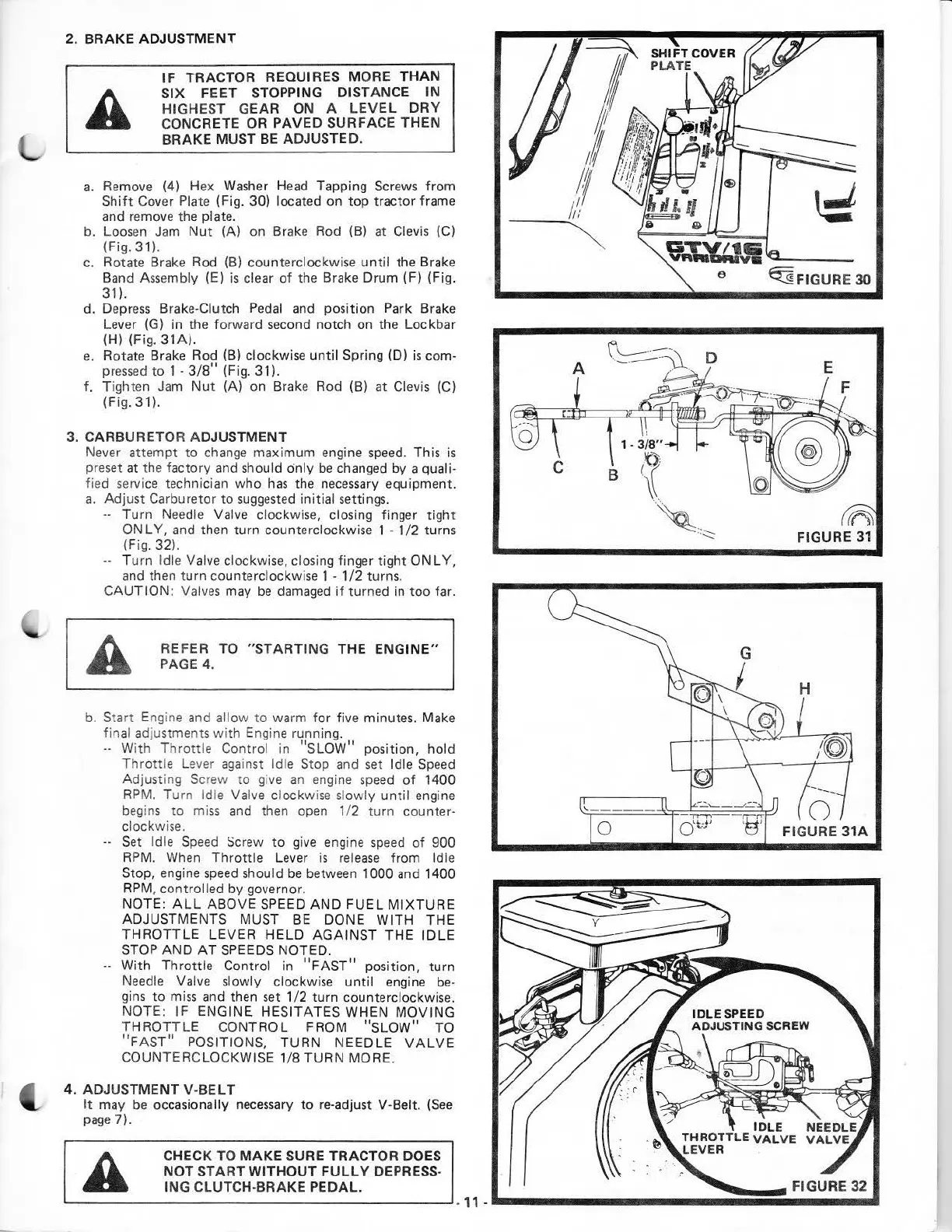
a.
Remove (4) Hex Washer Head Tapping Scre
ws
from
Shift
Cover Plate (Fig. 30) located on
top
tractor
frame
and remove the plate.
b. Loos
en
Jam
Nut
(A) on Brake Rod
(B)
at Clevis (C)
(Fig. 31).
c.
Rotate Brake Rod
(B)
counterclockwi
se
unt
il the Brake
Band Assembly (E)
is
clear
of
t
he
Brake Drum (F) (Fig.
31
).
d. Depress Brake-Clutch
Pedal
and position Park Brake
Lever (G) in the
fo
rward second notch on the Lockbar
(H) (Fig.
31A)
.
e.
Rotate Brake Rod (B) clockwise
until
Spring (D)
is
com-
pressed
to
1 -
3/8"
(Fig. 31).
f.
Tight
en
Jam
Nut
(A) on Brake Rod (B)
at
Clevis
(C)
(Fig. 31).
3.
CARBURETOR
ADJUS
TMENT
Never
attempt
to
change
maximum
eng
ine
speed
. This
is
preset at the factory and should only
be
changed by a quali-
fied servi
ce
technician
who
has
the necessary equipment.
a. Adjust Carburetor
to
suggested
initial settings.
.. Turn Needle Valve clockwise, closing finger
tight
ONLY,
and then turn counterclockwise 1 -
1/2
turns
(Fig. 32).
--
Turn Idle
Va
lve clockwise, closi
ng
finger
tight
ONLY,
and then
turn
counterclockwise 1 -
1/2
turns.
CAUTION
: Valves may
be
damaged
if
turned in
too
far.
REFER TO
"STARTING
THE
ENGINE"
PAGE
4.
b.
Sta
rt Engine and
al
l
ow
to warm
for
five minutes. Make
fin
al adjustments
with
Engine running .
.. With Thro
ttle
Control in
"SLOW"
pos
i
tion,
hold
T
hr
ottle Lever against Idle Stop
and
set Idle Speed
Ad
justing Screw
to
give an
eng
ine
speed
of
1400
RP
M. T
urn
Idle
Va
l
ve
cl
ockw
ise sl
ow
ly
unt
il engine
begins
to
miss
and
then open 1/ 2 t
urn
counter-
clockwise.
--
Set Idle
Spee
d
Sc
rew
to
give
engine
speed
of
900
RPM. When
Thrott
le Lever
is
rel
ease
from Idle
Stop,
engine
speed
should
be
between 1000
and
1400
RPM
, controlled by governor.
NOTE:
ALL
ABOVE SPEED
AND
FUEL
MIXTURE
ADJUSTMENTS MUST
BE
DONE
WITH
THE
THROTTLE
LEVER
HELD
AGAINST
THE
IDLE
STOP
AND
AT
SPEEDS NOTED.
··
With
Th
r
ott
le Control in
"FAST"
position, turn
Needle Val
ve
slowly
clockw
i
se
until
engine
be·
gins
to
mi
ss
and then
set
1/2 t
urn
counterclockwise.
NOTE:
IF
ENGINE HESITATES WHEN
MOVING
THROTTLE
CONTROL FROM
"SLOW"
TO
"
FAST"
POSITIONS,
TURN
NEEDLE
VALVE
COUNTERCLOCKWISE 1
/8
TURN
MORE.
4.
ADJUSTMENT
V-BELT
It
may
be occasionally necessary
to
re-adjust V-Belt.
(See
page
7).
D
1.
3/8"
B
(
~?
l .
~
--
..
~
tR\
FIGURE
31
another free manual from www.searstractormanuals.com