GB
SEC Electronics PKN10 V0.3 page 4
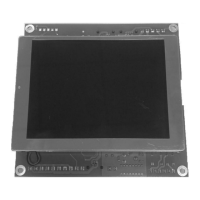
K1: (8-pin RJ-45 connector): SSL input
K2: (8-pin RJ-45 connector): SSL output
K3: (5-way 5,08 mm terminal block): external 24 V DC power
supply and 12 V, 1,3 Ah battery connection
K5: (2-way 5,08 mm terminal block): speaker output (max. 5W,
min. 4 ohm)
K6: Micro SD card socket
K7: (10-way 5,08 mm terminal block): inputs and outputs, see
figure 2 and the description below
K8: (6/4-pin RJ-11 connector): direction indicator outputs
K9: (6-way 3,91 mm terminal block): emergency call disable relay
K10: (5-way 3,91 mm terminal block): CAN communication link
(currently not used)
J1, J2: jumpers to select power supply via SSL (closed) or external
power supply via K3 (open)
J3, J4: CAN bus termination (currently not used)
D1: green LED (ON when device is working properly, blinking when
communication doesn’t work).
D2: green LED (CAN communication status, currently not used)
D3: red LED (ON, when audio output is active)
D4: green LED (ON when Micro SD card is inserted)
K7 terminal description:
terminal 1: 24 V DC (from external power supply)
terminal 2: call DOWN
terminal 3: 0V
terminal 4: 24 V DC
terminal 5: call UP
terminal 6: 0V
terminal 7: multifunction input 4
terminal 8: multifunction input 3
terminal 9: multifunction input 2
terminal 10: multifunction input 1
Terminal 1 is in Figure 2 on the left side.
K8 pinout:
pin 1: 0V
pin 2: indicator up
pin 3: indicator down
pin 4: 0V
Pin 1 is in Figure 2 on the left side.