IV User Adjustments
Series 600HS units are gasket-sealed. Changes or adjustments to the operating modes of any unit
are accomplished internally:
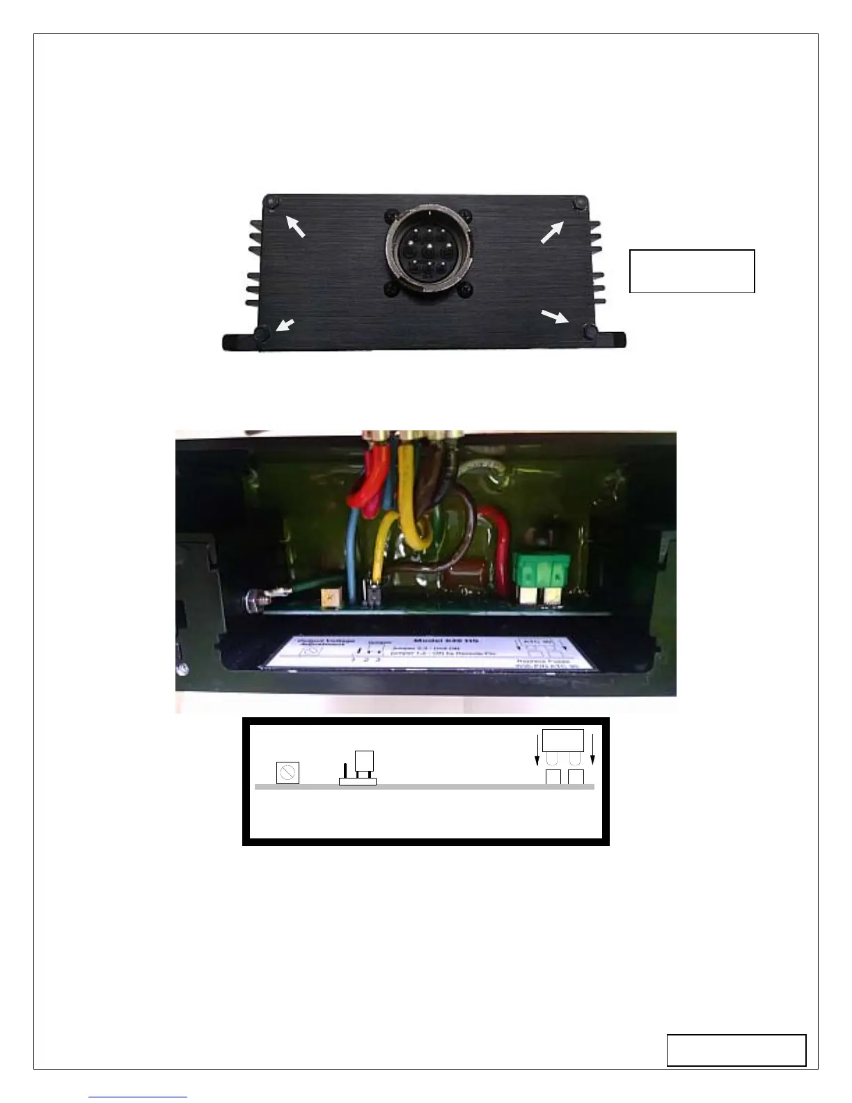
1) To gain access, remove the 4 corner screws retaining the connector plate as shown in Figure
#4. Disconnect power from the unit before opening it.
2) After removing the screws, lift the panel to expose the internal components as shown. Figure
#5 shows the adjustments and their locations
With P/N ATC 30
Replace Fuses
ATC 30
1
2
3
jumper 2,3 - Unit ON
jumper 1,2 - ON by Remote Pin
Output Voltage
Adjustment
jumper
P1
CON1
F1,2
Figure 5
Accessible Adjustments:
A) Output voltage is trimmed by adjusting the potentiometer P1.
B) Remote “Turn On” Disabled: Units are shipped from factory with pins 2 and 3 of the
connector [CON1] jumpered as shown. This programs the unit to be “ON” when source power
is applied.
C) Remote “Turn On” Enabled: To program the unit for remote enable, shift the jumper from
pin positions 2 and 3 of [CON1] to positions 1 and 2. In this mode the unit will energize when
pin H is connected to the negative input line pin F.
Page 3
Figure 4